K3HB-X
Process Indicator
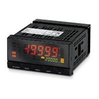
A Process Indicator Ideal for Discriminating and Displaying Measurements for Voltage/Current Signals
Related Contents
 Application Solutions
- Features
- Lineup
- Specifications
- Dimensions
- Catalog / Manual / CAD / Software
last update: July 1, 2026
Ratings
| Power supply voltage | 100 to 240 VAC (50/60 Hz), 24 VAC/VDC | |
|---|---|---|
| Allowable power supply voltage
range |
85% to 110% of the rated power supply voltage | |
| Power consumption *1 | 100 to 240 V: 18 VA max. (max. load)
24 VAC/DC: 11 VA/7 W max. (max. load) |
|
| Input | DC voltage, DC current, AC voltage, AC current | |
| A/D conversion method | Delta-Sigma method | |
| External power supply | 12 VDC ±10%, 80 mA (models with external power supply only) | |
| Event
inputs *2 |
Timing input | NPN open collector or no-voltage contact signal
ON residual voltage: 3 V max. ON current at 0 Ω: 17 mA max. Max. applied voltage: 30 VDC max. OFF leakage current: 1.5 mA max. |
| Startup compensation
timer input |
NPN open collector or no-voltage contact signal
ON residual voltage: 2 V max. ON current at 0 Ω: 4 mA max. Max. applied voltage: 30 VDC max. OFF leakage current: 0.1 mA max. |
|
| Hold input | ||
| Reset input | ||
| Forced-zero input | ||
| Bank input | ||
| Output
ratings (depends on the model) |
Relay output | 250 VAC, 30 VDC, 5 A (resistive load)
Mechanical life expectancy: 5,000,000 operations (UL not applicable), Electrical life expectancy: 50,000 operations |
| Transistor output | Maximum load voltage: 24 VDC, Maximum load current: 50 mA, Leakage current:
100 μA max. |
|
| Linear output | Linear output 0 to 20 mA DC, 4 to 20 mA DC:
Load: 500 Ω max, Resolution: Approx. 10,000, Output error: ±0.5% FS Linear output 0 to 5 VDC, 1 to 5 VDC, 0 to 10 VDC: Load: 5 kΩ max, Resolution: Approx. 10,000, Output error: ±0.5% FS (1 V or less: ±0.15 V; no output for 0 V or less) |
|
| Display method | Negative LCD (backlit LED) display
7-segment digital display (Character height: PV: 14.2 mm (green/red); SV: 4.9 mm (green) |
|
| Main functions | Scaling function, measurement operation selection, averaging, previous average
value comparison, forced-zero, zero-limit, output hysteresis, output OFF delay, output test, teaching, display value selection, display color selection, key protection, bank selection, display refresh period, maximum/minimum hold, reset |
|
| Ambient operating temperature *3 | -10 to 55 °C (with no icing or condensation) | |
| Ambient operating humidity | 25% to 85% | |
| Storage temperature | -25 to 65 °C (with no icing or condensation) | |
| Altitude | 2,000 m max. | |
| Accessories | Watertight packing, 2 fixtures, terminal cover, unit stickers, instruction manual. | |
*1. DC power supply models require a control power supply capacity of approximately 1 A per Unit when power is turned
ON. Particular attention is required when using two or more DC power supply models. The OMRON S8VS-series DC
Power Supply Unit is recommended.
*2. PNP input types are also available.
*3. Use models with relay output (C2) at an ambient temperature of 50°C or lower.
Characteristics
| Display range | -19,999 to 99,999 | |
|---|---|---|
| Sampling period | 20 ms (50 times/second) | |
| Comparative output
response time |
DC input: 100 ms max.; AC input: 300 ms max.
(The time until the comparative output is output when there is a forced sudden change in the input signal from 15% to 95% or 95% to 15%.) |
|
| Linear output response
time |
DC input: 150 ms max.; AC input: 420 ms max.
(The time until the final analog output value is reached when there is a forced sudden change in the output signal from 15% to 95% or 95% to 15%.) |
|
| Insulation resistance | 20 MΩ min. (at 500 VDC) | |
| Dielectric strength | 2,300 VAC for 1 min between external terminals and case | |
| Noise immunity | 100 to 240 VAC models: ±1,500 V at power supply terminals in normal or common mode
(waveform with 1-ns rising edge and pulse width of 1 μs/100 ns) 24 VAC/VDC models: ±1,500 V at power supply terminals in normal or common mode (waveform with 1-ns rising edge and pulse width of 1 μs/100 ns) |
|
| Vibration resistance | Frequency: 10 to 55 Hz; Acceleration: 50 m/s2, 10 sweeps of 5 min each in X, Y, and Z
directions |
|
| Shock resistance | 150 m/s2 (100 m/s2 for relay outputs) 3 times each in 3 axes, 6 directions | |
| Weight | Approx. 300 g (Base Unit only) | |
| Degree of protection
(UL not applicable) |
Front panel | Conforms to NEMA 4X for indoor use (equivalent to IP66) |
| Rear case | IP20 | |
| Terminals | IP00 + finger protection (VDE0106/100) | |
| Memory protection | EEPROM (non-volatile memory)
Number of rewrites: 100,000 |
|
| Applicable standards * | UL/CSA 61010-1, UL/CSA 61010-2-030
EN/IEC 61010-1, EN/IEC 61010-2-030 Pollution degree 2/Overvoltage category II EN61326-1 |
|
| EMC | EMI: EN61326-1 Industrial electromagnetic environment
Electromagnetic radiation interference: CISPR 11 Group 1, Class A Terminal interference voltage: CISPR 11 Group 1, Class A EMS: EN61326-1 Industrial electromagnetic environment Electrostatic Discharge Immunity: EN61000-4-2: 4 kV (contact), 8 kV (in air) Radiated Electromagnetic Field Immunity: EN61000-4-3: 10 V/m 1 kHz sine wave amplitude modulation (80 MHz to 1 GHz, 1.4 to 2 GHz) Electrical Fast Transient/Burst Immunity: EN61000-4-4: 2 kV (power line), 1 kV (I/O signal line) Surge Immunity: EN61000-4-5: 1 kV with line (power line), 2 kV with ground (power line) Conducted Disturbance Immunity: EN61000-4-6: 3 V (0.15 to 80 MHz) Power Frequency Magnetic Immunity: EN61000-4-8: 30 A/m (50 Hz) continuous time Voltage Dips and Interruptions Immunity: EN61000-4-11: 0.5 cycle, 0°/180°, 100% (rated voltage) |
|
* Models equipped with relay output (C2) are cURus certified.
Input Range (Measurement Range and Accuracy)
| Input
type |
Range | Set
value |
Measurement
range |
Maximum
measurement range |
Input
impedance |
Accuracy | Allowable
instantaneous overload (30 s) |
|---|---|---|---|---|---|---|---|
| K3HB-XVD
DC voltage (CAT II) |
A |  |
±199.99 V | -19.999 to 21.999 V | 10 MΩ min. | ±0.1%rdg
± 1 digit max. |
±400 V |
| B |  |
±19.999 V | -19.999 to 21.999 V | 1 MΩ min. | ±200 V | ||
| C |  |
±1.9999 V | -19.999 to 21.999 V | ||||
| D |  |
1.0000
to 5.0000 V |
0.5000
to 5.5000 V |
||||
| K3HB-XAD
DC current |
A |  |
±199.99 mA | 199.99
to 219.99 mA |
1 Ω max. | ±0.1%rdg
± 1 digit max. |
±400 mA |
| B |  |
±19.999 mA | 19.999
to 21.999 mA |
10 Ω max. | ±200 mA | ||
| C |  |
±1.9999 mA | 1.9999
to 2.1999 mA |
33 Ω max. | |||
| D |  |
4.000
to 20.000 mA |
2.000
to 22.000 mA |
10 Ω max. | |||
| K3HB-XVA
AC voltage *4 (CAT II) |
A |  |
0.0 to 400.0 V | 0.0 to 440.0 V | 1 MΩ min. | ±0.3%rdg
± 5 digits max. |
700 V |
| B |  |
0.00
to 199.99 V |
0.00
to 219.99 V |
||||
| C |  |
0.00
to 199.99 V |
0.000
to 21.999 V |
±0.5%rdg
± 10 digits max. |
400 V | ||
| D |  |
0.0000
to 1.9999 V |
0.0000 to 1.9999 V | ||||
| K3HB-XAA
AC current |
A |  |
0.000
to 10.000 A |
0.000
to 11.000 A |
(0.5 VA CT)
*3 |
±0.5%rdg
± 20 digits max. |
20 A |
| B |  |
0.0000
to 1.9999 A |
0.0000
to 2.1999 A |
(0.5 VA CT)
*3 |
|||
| C |  |
0.00
to 199.99 mA |
0.00
to 219.99m A |
1 Ω max. | ±0.5%rdg
± 10 digits max. |
2 A | |
| D |  |
0.000
to 19.999 mA |
0.000
to 21.999m A |
10 Ω max. |
*1. The accuracy is for an input frequency range of 40 Hz to 1 kHz (except for AD current input A and B ranges of 50 to
60 Hz) and an ambient temperature of 23 ±5°C. The error, however, increases below 10% of the maximum input
value.
DC voltage input (all ranges): 10% or less of max. input = ±0.15% FS
DC current input (all ranges): 10% or less of max. input = ±0.1% FS
AC voltage input (A: 0.0 to 400.0 V): 10% or less of max. input = ±0.15% FS
AC voltage input (B: 0.00 to 199.99 V): 10% or less of max. input = ±0.2% FS
AC voltage input (C: 0.000 to 19.999 V; D: 0.0000 to 1.9999 V): 10% or less of max. input = ±1.0% FS
AC current input (A: 0.000 to 10.000 A): 10% or less of max. input = ±0.25% FS
AC current input (B: 0.0000 to 1.9999 A): 10% or less of max. input = ±0.5% FS
AC current input (C: 0.00 to 199.99 mA; D: 0.000 to 19.999 A): 10% or less of max. input = ±0.15% FS
When DC voltage input models are used with a ±1.9999 V range, make sure that the connections between input
terminals are not open.
If the input terminals are open, the display will show large variations. Connect resistance of approximately 1 MΩ
between the input terminals if they are open.
*2. The letters "rdg" mean "reading" and refer to the input error.
*3. The value (0.5 VA CT) is the VA consumption of the internal CT (current transformer).
60 Hz) and an ambient temperature of 23 ±5°C. The error, however, increases below 10% of the maximum input
value.
DC voltage input (all ranges): 10% or less of max. input = ±0.15% FS
DC current input (all ranges): 10% or less of max. input = ±0.1% FS
AC voltage input (A: 0.0 to 400.0 V): 10% or less of max. input = ±0.15% FS
AC voltage input (B: 0.00 to 199.99 V): 10% or less of max. input = ±0.2% FS
AC voltage input (C: 0.000 to 19.999 V; D: 0.0000 to 1.9999 V): 10% or less of max. input = ±1.0% FS
AC current input (A: 0.000 to 10.000 A): 10% or less of max. input = ±0.25% FS
AC current input (B: 0.0000 to 1.9999 A): 10% or less of max. input = ±0.5% FS
AC current input (C: 0.00 to 199.99 mA; D: 0.000 to 19.999 A): 10% or less of max. input = ±0.15% FS
When DC voltage input models are used with a ±1.9999 V range, make sure that the connections between input
terminals are not open.
If the input terminals are open, the display will show large variations. Connect resistance of approximately 1 MΩ
between the input terminals if they are open.
*2. The letters "rdg" mean "reading" and refer to the input error.
*3. The value (0.5 VA CT) is the VA consumption of the internal CT (current transformer).

*4. The K3HB-XVA[][] complies with UL standards when the applied input voltage is within the range 0 to 150 VAC. If the input voltage exceeds 150 VAC, install an external transformer or take other measures to reduce the voltage to 150 VAC or lower. Do not use the K3HB-XAD[][] or K3HB-XAA[][] for measurement of commercial power supplies. Also, do not use them for measurement of circuits where the applied voltage exceeds 30 Vr.m.s. or 60 VDC. When using the K3HB-XAA[][] in a Measurement Category II environment, use an external CT that is UL/cUL Listed (Certification Category: XOBA/7), and ensure that appropriate measures are taken in the final equipment.
last update: July 1, 2026
 Top of page