CJ1W-PDC15
CJ-series Process Analog I/O Unit
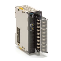
A Single Unit Handling All Types of Inputs such as Temperature Sensor Inputs and Analog Signal Inputs (e.g., 4 to 20 mA or 1 to 5 V). This unit is available for CJ/NJ controller.
Related Contents
- Features
- Lineup
- Specifications
- Dimensions
- Catalog / Manual / CAD / Software
last update: September 24, 2012
| Item | Specifications | |
|---|---|---|
| Model | CJ1W-PDC15 | |
| Applicable Controller | CJ/NJ Series | |
| Unit classification | CJ-series Special I/O Unit | |
| Mounting position | CPU Rack or Expansion Rack | |
| Maximum number of Units | 40 (within the allowable current consumption and power consumption range) | |
| Unit numbers | 00 to 95 (Cannot duplicate Special I/O Unit numbers.) | |
| Areas for data exchange with CPU Unit | Special I/O Unit Area (Operation Data) | 10 words/Unit Direct Current Input Unit to CPU Unit: All process values, process value alarms (LL, L, H, HH), rate-of-change values, rate-of-change alarms (L, H), disconnection alarms, cold junction sensor errors, adjustment period end/notice |
| DM Area words allocated to Special I/O Units (Setting parameter) | 100 words/Unit CPU Unit to Direct Current Input Unit: Input signal type, scaling of process value in industrial units, process value alarm setting (L, H), inrush input upper limit, inrush input upper limit time, zero/span adjustment value, Square root function. Temperature input signal type, input range (user set), scaling of process value data to be stored in allocated words in CIO area, rate-of-change input range, scaling of rate-of-change data, number of items for moving average, process value alarm setting (LL, L, H, HH), rate-of-change alarm setting (L, H), zero/span adjustment value | |
| Expansion Control/ Monitor Area (Expansion Operation Data) | 35 words/Unit CPU Unit to Direct Current Input Unit: Bits for beginning or resetting the hold function selection, adjustment period control, control bits Direct Current Input Unit to CPU Unit: Adjustment period notices, peak and bottom values, top and valley values, integral values | |
| Expansion Setting Area (Expansion Setting parameter) | 46 words/Unit CPU Unit to Direct Current Input Unit: Expansion Setting Area settings, adjustment period control, peak and bottom detection, top and valley detection, integral value calculation | |
| Number of inputs | 2 | |
| Input signal type | 4 to 20 mA, 0 to 20 mA, 0 to 10 V, -10 to 10 V, 0 to 5 V, -5 to 5 V, 1 to 5 V, 0 to 1.25 V, -1.25 to 1.25 V (separate for each input), and ±10-V user-set range (specified range within -10.000 V to 10.000 V) | |
| Scaling | Data to be stored in the allocated words in the CIO area must be scaled (Any minimum and maximum values can be set.) (2 inputs set separately.) Data can be converted at 0% to 100%. | |
| Data storage in the CIO Area | The value derived from carrying out the following processing in order of the actual process data in the input range is stored in four digits hexadecimal (binary values) in the allocated words in the CIO Area. 1) Mean value processing → 2) Scaling → 3) Zero/span adjustment → 4) Square root calculation → 5) Output limits | |
| Accuracy (25 ° C) | ±0.05% | |
| Temperature coefficient | ±0.008%/°C | |
| Resolution | 1/64,000 | |
| Input signal range | For 4 to 20 mA, 0 to 20 mA, 0 to 10 V, 0 to 5 V, 1 to 5 V, 0 to 1.25 V inputs: -15 to 115% For -10 to 10 V, -5 to 5 V, -1.25 to 1.25 V inputs: -7.5 to 107.5% | |
| Input impedance | For current inputs: 250 Ω (typical) For voltage inputs: 1 MΩ min. | |
| Warmup time | 10 min | |
| Conversion period | 10 ms/2 inputs | |
| Maximum time to store data in CPU Unit | Conversion period + one CPU Unit cycle | |
| Input error detection | Check only for 4 to 20 mA and 1 to 5 V. Error detected for -17.2% (1.25 mA, 0.3125 V) or less and 112.5% (22 mA, 5.5 V) or more. | |
| Operation at input disconnection | For 4 to 20 mA and 1 to 5 V: Stores -15% process value. For all other ranges: Stores same process value as 0-V or 0-mA inputs. | |
| Input disconnection detection delay time | Approx. 1 s. | |
| Function | Mean value processing (input filter) | Calculates the moving average for the past specified number of process values (1 to 128 can be specified), and stores that value in the CIO Area as the process value. |
| Process value alarm | Process value 4-point alarm (LL, L H, HH), hysteresis, and ON-delay timer (0 to 60 s) are available. | |
| Rate-of-change calculation | Calculates the amount of change per comparison time interval (1 to 16 s). | |
| Rate-of-change alarm | Rate-of-change 2-point alarm (H, L), alarm hysteresis, and ON-delay timer (0 to 60 s are available, shared with process value alarm). | |
| Square root calculation | When the maximum value for process value scaling is A and the minimum value is B, Drop-out: Output approx. 7% max. linear (output = input) characteristic Note 1. The square root function can only be used when the maximum scaling value is greater than the minimum scaling value. The square root will not be found if the maximum is smaller than the minimum. Note 2. When the square root function is used, set the scaling values after square root calculation (e.g., for flow rates or other values) for the process value scaling A and B settings. | |
| Adjustment period control | When zero/span adjustment is executed, the date is internally recorded at the Unit. When the preset zero/span adjustment period and the notice of days remaining set in the Expansion Setting Area have elapsed, this function turns ON a warning flag to give notice that it is time for readjustment. | |
| Peak and bottom detection | Detects the maximum (peak) and minimum (bottom) analog input values, from when the Hold Start Bit (output) allocated to the Expansion Control/Monitor Area turns ON until it turns OFF. These values are stored as the peak and bottom values in the Expansion Control/Monitor Area. | |
| Top and valley detection | This function detects the top and valley values for analog inputs, from when the Hold Start Bit (output) allocated to the Expansion Control/Monitor Area turns ON until it turns OFF. These values are stored as the top and valley values in the Expansion Control/Monitor Area. | |
| Integral value calculation | This function calculates the analog input value's time integral. The integral value is calculated and output to the Expansion Control/Monitor Area when the Integral Value Calculation Start Bit in the Expansion Control/Monitor Area is turned ON. | |
| Isolation | Between inputs and between inputs and Controller signals: Isolation by transformer and photocoupler. | |
| Insulation resistance | 20 MΩ (at 500 V DC) between all inputs | |
| Dielectric strength | Between inputs: 1,000 V AC, at 50/60 Hz, for 1 min, leakage current 10 mA max. | |
| External connections | Terminal block (detachable) | |
| Unit number settings | Set by rotary switches on front panel, from 0 to 95. | |
| Indicators | Four LED indicators on front panel (for normal operation, errors detected at the Direct Current Input Unit, and errors detected at the CPU Unit). | |
| Front panel connector | Sensor input connector terminal block (detachable) | |
| Current consumption | 5 V DC at 180 mA max. | |
| External power supply | 24 V DC +10%/-15% 90 mA max., inrush current: 20 A for 1 ms max. (The external 24-VDC power supply must be isolated.) | |
| Dimensions | 31 × 130 × 65 mm (W × H × D) | |
| Weight | 150 g max. | |
| Standard accessories | Short bars (for current input) | |
last update: September 24, 2012