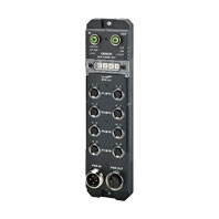
NXR-ILM08C-ECT
Environment-resistive Remote Terminal NXR-series IO-Link Master Unit for EtherCAT®

Streamline commissioning and maintenance efforts and stabilize operation
- Features
- Lineup
- Specifications
- Dimensions
- Catalog / Manual / CAD / Software
last update: December 18, 2023
General Specifications
| Item | Specification | |
|---|---|---|
| Degree of protection | IP67 | |
| Operating
environment |
Ambient operating temperature | -10 to 55°C |
| Ambient operating humidity | 25% to 85% (with no condensation) | |
| Ambient operating atmosphere | Must be free from corrosive gases. | |
| Storage temperature | -25 to 65°C | |
| Storage humidity | 25% to 85% (with no condensation) | |
| Altitude | 2,000 m max. | |
| Pollution degree | 3 or less: Conforms to IEC 61010-2-201. | |
| Noise immunity | 2 kV on power supply line (Conforms to IEC 61000-4-4.) | |
| Overvoltage category | Category II: Conforms to IEC 61010-2-201. | |
| EMC immunity level | Zone B | |
| Vibration resistance | 10 to 60 Hz with amplitude of 0.35 mm, 60 to 150 Hz and 50 m/s2
for 80 minutes each in X, Y, and Z directions. |
|
| Shock resistance | 150 m/s2, 3 times each in 6 directions along X, Y, and Z axes | |
| Dielectric strength | 600 VAC (between isolated circuits) | |
| Insulation resistance | 20 MΩ min. (between isolated circuits) | |
| Applicable standards *1 | cULus: Listed (UL61010-2-201)
EU: EN 61131-2, RCM KC: KC Registration UKCA IO-Link conformance EtherCAT conformance |
|
*1. Ask your OMRON representative for the most recent applicable standards.
EtherCAT Communications Specifications
| Item | Specification |
|---|---|
| Communications protocols | EtherCAT protocol |
| Modulation | Baseband |
| Link speed | 100 Mbps |
| Physical layer | 100BASE-TX (IEEE802.3) |
| Connectors | M12 (D-coding, female) x 2 (shielded)
CN IN: EtherCAT input CN OUT: EtherCAT output |
| Topology | Depends on the specifications of the EtherCAT master *1*2 |
| Transmission media | Category 5 or higher twisted-pair cable (Recommended cable: doubleshielded
cable with aluminum tape and braiding) |
| Transmission distance | Distance between nodes (slaves): 50 m or less |
| Noise immunity | Conforms to IEC 61000-4-4, 1 kV or more |
| Node address setting method | Setting with hexadecimal ID switch or Configuration Software |
| Node address range *3 | • Setting with hexadecimal ID switch: 01 to FF hex (1 to 255)
• Setting with Configuration Software: 0001 to FFFF hex (1 to 65,535) |
| Indicators | L/A IN (Link/Activity IN) x 1
L/A OUT (Link/Activity OUT) x 1 RUN x 1 ERR x 1 |
| Process data | Variable PDO mapping |
| PDO size/node | Input: 1 to 270 bytes
Output: 2 to 258 bytes |
| Mailbox | Emergency messages, SDO requests, and SDO responses |
| Synchronization type | Free-Run Mode (Asynchronous) |
*1. The IO-Link Master Unit conforms to the EtherCAT standards. Confirm the specifications of the connected EtherCAT
master for the supported topology. Note that the IO-Link Master Unit supports the ring topology.
*2. For the ring topology, the minimum value of the supported communications cycle is 125 μs. Allowing the IO-Link Master
Unit to operate with a shorter communications cycle than the minimum value may cause the loss of EtherCAT
communications frames or a communications stop.
*3. The setting range of the node address depends on the specifications of the connected EtherCAT master. Check the
specifications of the EtherCAT master for the supported node address setting range of the EtherCAT master.
Unit Specifications
| Item | Specification | |
|---|---|---|
| IO-Link
specifications |
IO-Link connector type | Class A |
| Communications protocol | IO-Link protocol | |
| Number of ports | 8 | |
| Baud rate | COM1: 4.8 kbps
COM2: 38.4 kbps COM3: 230.4 kbps |
|
| Topology | 1:1 | |
| Compliant standards | • IO-Link Interface and System Specification Version1.1.2
• IO-Link Test Specification Version1.1.2 |
|
| Cable specifications | • Cable type: Unshielded
• Cable length: 20 m max. • Electrostatic capacity between lines: 3 nF max. • Loop resistance: 6 Ω max. |
|
| Unit/input power supply voltage | 24 VDC (20.4 to 26.4 VDC) | |
| Output power supply voltage | 24 VDC (20.4 to 26.4 VDC) | |
| Maximum power supply current | 9 A
Sum of Unit/input power supply current and output power supply current |
|
| Number of connected Units when supplying
power with through-wiring |
No restrictions if power supply specifications are met. | |
| Mounting method | Mounting with M5 screws | |
| Mounting strength | 100 N | |
| Installation orientation and restrictions | Installation orientation: 6 possible orientations
Restrictions: No restrictions |
|
| Connector types | • EtherCAT communications connectors: M12 (D-coding, female) × 2
• Power supply connectors: 7/8 inch (male) × 1, 7/8 inch (female) × 1 • I/O connectors: M12 (A-coding, female) × 8 |
|
| Connector strength | 30 N
Applicable to all connectors |
|
| Screw tightening torque | • EtherCAT communications connectors and I/O connectors
(M12 screw): 0.5 to 0.6 N·m • Power supply connectors (7/8 inch screw): 1.5 to 1.7 N·m • Unit mounting (M5 screw): 1.47 to 1.96 N·m • Rotary switch cover (M3 screw): 0.4 to 0.6 N·m • Waterproof covers for EtherCAT communications connectors (M12 screw): 0.5 to 0.6 N·m • Waterproof covers for power supply connectors (7/8 inch screw): 1.5 to 1.7 N·m |
|
| Maximum port current | 4 A/port
Total available current between pin 1 and pin 4 |
|
| Device power
supply *1 in IO-Link Mode or SIO (DI) Mode |
Power supply used | Unit/input power supply |
| Rated voltage | 24 VDC (20.4 to 26.4 VDC) | |
| Maximum load current | 2 A/pin | |
| Short-circuit protection | Provided *2 | |
| Short-circuit detection | Provided *2 | |
| Digital inputs
for pin 4 or digital inputs for pin 2 (in SIO (DI) Mode) |
Power supply used | Unit/input power supply |
| Rated voltage | 24 VDC (20.4 to 26.4 VDC) | |
| Internal I/O common | PNP | |
| Input current | • Digital inputs for pin 2: 3.0 mA (at 24 VDC)
• Digital inputs for pin 4: 6.3 mA (at 24 VDC) |
|
| ON voltage/ON current | • Digital inputs for pin 2: 15 VDC min., 2 mA min.
• Digital inputs for pin 4: 15 VDC min., 3 mA min. |
|
| OFF voltage/OFF current | 5 VDC max., 1 mA max. | |
| ON/OFF response time | 1.0 ms max. | |
| Input filter time | No filter, 0.25 ms, 0.5 ms, 1 ms (default), 2 ms, 4 ms, 8 ms, 16 ms,
32 ms, 64 ms, 128 ms, 256 ms |
|
| Short-circuit protection | Provided *2 | |
| Short-circuit detection | Provided *2 | |
| Digital outputs
for pin 4 or digital outputs for pin 2 (in SIO (DO) Mode) |
Power supply used | Output power supply |
| Internal I/O common | PNP | |
| Output type | Open-drain | |
| Rated voltage | 24 VDC (20.4 to 26.4 VDC) | |
| Maximum load current | 2 A/pin | |
| Leakage current | 0.1 mA max. | |
| Residual voltage | 1.5 V max. | |
| ON/OFF response time | 1.0 ms max. | |
| Short-circuit protection | Provided *3 | |
| Short-circuit detection | Provided *3 | |
| Current
consumption |
Unit/input power supply | 60 mA |
| Output power supply | 100 mA | |
| Weight | 440 g | |
| Dimensions | 240 × 24.2 × 62 mm (W × H × D)
(The height is 38 mm when the connectors are included.) |
|
| Isolation method | No isolation | |
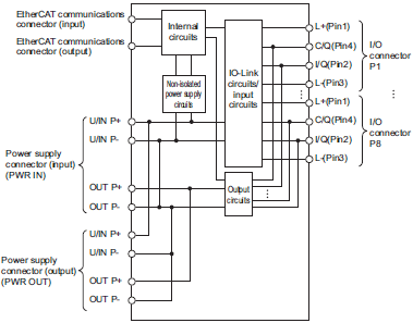
| Circuit layout |  |
|
*1. Used as a power supply for IO-Link devices or non-IO-Link input devices. Supplies power from the Unit/input power
supply of the IO-Link Master Unit to external devices through I/O connectors.
*2. Detects a short-circuit that occurred between pin 1 and pin 3 to protect the IO-Link Master Unit.
*3. Detects a short-circuit that occurred between pin 2 and pin 3 and between pin 4 and pin 3 to protect the IO-Link Master
Unit.
Version Information
The following table describes the relationship between the unit version of the IO-Link Master Units and the versions of the Support Software. With a combination of the following unit version or later and the following version or higher, you can use all of the functions that are supported by that unit version of the IO-Link Master Unit.
| Unit version | Corresponding version of Support Software | |
|---|---|---|
| Sysmac Studio | CX-ConfiguratorFDT | |
| Ver.1.0 | Ver.1.57 | Ver. 3.01, or Ver. 2.59 with automatic update as of January 2024 applied |
last update: December 18, 2023

