A30NN / A30NL
Pushbutton Switches
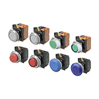
30-mm dia. Pushbutton Switches Control panel miniaturization through a more compact design and modified wiring direction. Addition of Push-In Plus terminal blocks for easy wiring. Workability and safety improvements.
Related Contents
- Features
- Lineup
- Specifications
- Dimensions
- Accessory
- Catalog / Manual / CAD / Software
last update: November 5, 2024
Specifications
(When the Operation Unit, LED Lamp, Mounting Collar, Contact Blocks, and Lighting Unit Are Combined)
Certified Safety Standard Ratings
UL508 Type 4X, 13 (File No. E76675), CSA C22.2 No.14
6 A 240 VAC, 10 A 120 VAC
TÜV (EN60947-5-1)
AC-15 3 A 240 VAC
DC-13 4 A 24 VDC
CCC (GB/T14048.5)
AC-15 3 A 240 VAC
DC-13 4 A 24 VDC
Application Standards
UL1059 and UL486E (Push-In Plus terminal block type)
Ratings
Contacts (Standard Load)
| Rated insulation voltage | 600 V | |||||
|---|---|---|---|---|---|---|
| Rated carry current | 10 A | |||||
| Rated voltage | 24 V | 120 V | 240 V | 380 V | 440 V | |
| AC at 50/60 Hz | Resistive load (AC-12) | 10 A | 10 A | 6 A | 2A | 2 A |
| Inductive load (AC-15) | 10 A | 6 A | 3 A | 1.9 A | 1.6 A | |
| DC | Resistive load (DC-12) | 8 A | 2.2 A | 1.1 A | -- | -- |
| Inductive load (DC-13) | 4 A | 1.1 A | 0.55 A | -- | -- | |
Note: 1. The above ratings were obtained by conducting tests under the following conditions.
(1) Ambient temperature: 20 ±2°C
(2) Ambient humidity: 65% ±5% RH
(3) Operating frequency: 30 operations/minute
2. Minimum applicable load: 10 mA at 5 VDC.
LED Lamps
| Rated voltage | Applied voltage | Rated current |
|---|---|---|
| 6 VAC/DC | 6 VAC/DC ±10% | Approx. 11 mA (red, orange, yellow, or blue)
Approx. 5 mA (white or green) |
| 12 VAC/DC | 12 VAC/DC ±10% | Approx. 12 mA (red, orange, yellow, or blue)
Approx. 5 mA (white or green) |
| 24 VAC/DC | 24 VAC/DC ±10% | Approx. 12 mA (red, orange, yellow, or blue)
Approx. 5 mA (white or green) |
| 100 VAC | 100 VAC ±10% | Approx. 12 mA (red, orange, yellow, or blue)
Approx. 5 mA (white or green) |
| 110 VAC | 110 VAC ±10% | |
| 120 VAC | 100 to 130 VAC | |
| 200 VAC | 200 VAC ±10% | Approx. 12 mA (red, orange, yellow, or blue)
Approx. 5 mA (white or green) |
| 220 VAC | 220 VAC ±10% | |
| 230 VAC | 230 VAC ±10% | |
| 240 VAC | 220 to 250 VAC |
Characteristics
| Item | Pushbutton Switches | ||
|---|---|---|---|
| Non-lighted models | Lighted models | ||
| Allowable operating
frequency |
Mechanical | 60 operations/minute max. | |
| Electrical | 30 operations/minute max. | ||
| Insulation resistance | 100 MΩ min. (at 500 VDC) | Not available for lighting units | |
| Contact resistance | 100 mΩ max. (initial value) | ||
| Dielectric strength | Between terminals
of same polarity |
2,500 VAC at 50/60 Hz for 1 min.
(initial value) |
Not available for lighting units |
| Between each
terminal and ground |
2,500 VAC at 50/60 Hz for 1 min. (initial value) | ||
| Vibration resistance | Malfunction | 10 to 55 Hz, 1.5-mm double amplitude (malfunction within 1 ms) | |
| Shock resistance | Malfunction | 1,000 m/s2 max. (malfunction within 1 ms) | |
| Durability | Mechanical | Momentary action: 5,000,000 operations min.
Alternate action: 500,000 operations min. |
|
| Electrical | 500,000 operations min.
(250 VAC, 3 A, with an inductive load having power factor cos θ = 0.4) |
||
| Ambient operating temperature *1 | -25 to 70°C | -25 to 55°C | |
| Ambient operating humidity | 35% to 85% RH | ||
| Ambient storage temperature *1 | -40 to 80°C | ||
| Degree of protection *2 | Compliant with IEC IP66, Certified for UL508 Type 4X, 13 | ||
| Electric shock protection class | Class II | ||
| PTI (tracking characteristic) | 175 | ||
| Degree of contamination
(application environment) |
3 (EN 60947-5-1) | ||
| Weight | Approx. 60 g (for 1NC/1NO) | Approx. 75 g (for 1NC/1NO) | |
*1. With no icing or condensation.
*2. Degree of protection from the front of the panel.
Operating Characteristics (for SPST-NO/SPST-NC)
| Item | Pushbutton Switches |
|---|---|
| Lighted/non-lighted | |
| Total travel force (torque) (maximum TTF) | 18 N |
| Total travel (TT) | 6 mm max. |
| Resetting force (torque) (RF) | -- |
Examples of Linked Contact Blocks (Screw terminal block type)

| Pushbutton Switches | ||||
|---|---|---|---|---|
| Momentary | Alternate | |||
| Lighted | Non-lighted | Lighted | Non-lighted | |
| Linking example |  |
 |
 |
 |
Note: If you increase the number of Contact Blocks, evaluate the Switch under actual working conditions before permanent installation and use the Switch within a number of switching operations that will not adversely affect the Switch’s performance.
last update: November 5, 2024