ZP-L
Laser Displacement Sensor
Premium detection stability and optimal usability for Laser Displacement Sensors
Related Contents
- Features
- Lineup
- Specifications
- Dimensions
- Catalog / Manual / CAD / Software
last update: February 2, 2026
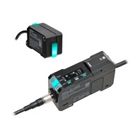
Sensor Head
| Item | Specification | ||||||
|---|---|---|---|---|---|---|---|
| ZP-LS025L(C) | ZP-LS025S(C) | ZP-LS050L(C) | ZP-LS050S(C) | ZP-LS100L(C) | ZP-LS100S(C) | ||
|
Reference
distance |
25 mm | 50 mm | 100 mm | ||||
|
Measurement
distance |
20 to 30 mm | 40 to 60 mm | 65 to 135 mm | ||||
| Light source | Red semiconductor laser | ||||||
| Wavelength | 660 nm | ||||||
| Laser class | ZP-LS[]L, ZP-LS[]S: Class 2 (JIS/IEC/EN/FDA/GB)
ZP-LS[]LC, ZP-LS[]SC: Class 1 (JIS/IEC/EN/FDA/GB) |
||||||
| Laser power | ZP-LS[]L, ZP-LS[]S: 1 mW max.
ZP-LS[]LC, ZP-LS[]SC: 0.376 mW max. |
||||||
| Spot diameter *1 | ±0.05% F.S.
(±5 μm) |
Approx.
50 μm dia. |
Approx.
70 × 1,600 μm |
Approx.
70 μm dia. |
Approx.
130 × 2,900 μm |
Approx.
120 μm dia. |
|
|
Linearity
*2 |
Near
side |
±0.05% F.S.
(±5 μm) |
±0.1% F.S.
(±10 μm) |
±0.03% F.S.
(±6 μm) |
±0.075% F.S.
(±15 μm) |
±0.025% F.S.
(±17.5 μm) |
±0.07% F.S.
(±49 μm) |
| when used at 20 to 25 mm | when used at 40 to 50 mm | when used at 65 to 100 mm | |||||
|
Total
area |
±0.08% F.S.
(±8 μm) |
±0.125% F.S.
(±12.5 μm) |
±0.04% F.S.
(±8 μm) |
±0.1% F.S.
(±20 μm) |
±0.065% F.S.
(±45.5 μm) |
±0.085% F.S.
(±59.5 μm) |
|
| when used at 20 to 30 mm | when used at 40 to 60 mm | when used at 65 to 135 mm | |||||
|
Resolution
(Repeatability) *3 |
0.5 μm | 0.6 μm | 0.7 μm | 0.8 μm | 1.2 μm | 1.3 μm | |
|
Temperature
characteristics *4 |
0.01% F.S./°C | 0.01% F.S./°C | 0.01% F.S./°C | ||||
| Indicators | 2 indicators (identified by color)
HIGH (orange)/PASS (green)/LOW (orange), Out of range (white), Error (red), SETTING mode (blue) |
||||||
|
Ambient
illuminance |
Illuminance of light-receiving surface, Incandescent lamp: 10,000 lx max. | ||||||
|
Ambient temperature
range |
Operating: -10 to 50°C, Storage: -15 to 70°C (with no icing or condensation) | ||||||
|
Ambient humidity
range |
Operating and storage: 35% to 85% RH each (with no condensation) | ||||||
|
Dielectric
strength |
1,000 VAC 50/60 Hz for 1 min. | ||||||
|
Insulation
resistance |
20 MΩ min. (at 500 VDC) | ||||||
|
Vibration
resistance |
10 to 500 Hz, double amplitude 1.5 mm, 120 min. each in X, Y and Z directions | ||||||
| Shock resistance | 300 m/s2, 3 times each in 6 directions along X, Y, and Z axes | ||||||
|
Degree of
protection |
IP67 (IEC60529) | ||||||
|
Connection
method *5 |
Pre-wired Connector type (Standard cable length: 2 m/0.2 m) | ||||||
| Material | Case and cover: Polybutylene terephthalate, Optical window: Glass, Threaded portion: SUS304, Cable: PVC | ||||||
|
Weight
(Main unit only) |
Approx. 90 g (Cable length: 2 m), Approx. 45 g (Cable length: 0.2 m) | ||||||
| Accessories | Instruction manual, compliance sheet, FDA certification label, fixing screws (M3 × 30 mm. 2 screws),
laser warning label (ZP-LS[]L and ZP-LS[]S models only) |
||||||
*1. This is the value (actual value) at the standard distance, which is defined as 1/e2 (13.5%) of the central light intensity.
*2. This shows the error of displacement output relative to the ideal line when OMRON’s standard target
(white diffuse object) is measured.
Linearity and measured values may vary depending on the target object.
F.S. refers to the entire measuring range (70 mm for ZP-LS100L).
*3. This shows the width of the variation of measured values when OMRON’s standard target (white diffuse object) is
measured at a reference distance with a measurement cycle of 1 ms and an average rate of 128 times.
*4. This is the value (typical value) measured at the reference distance, with the Sensor Head and OMRON’s standard object
(white diffuse object)
fixed with an aluminum jig between them.
*5. This product is powered by the Laser Displacement Sensor Amplifier Unit (ZP-L3[][][]).
| Item | Specification | ||||
|---|---|---|---|---|---|
| ZP-LS300L(C) | ZP-LS300S(C) | ZP-LS600L(C) | ZP-LS600S(C) | ||
|
Reference
distance |
300 mm | 600 mm | |||
|
Measurement
distance |
150 to 450 mm | 200 to 1,000 mm | |||
| Light source | Red semiconductor laser | ||||
| Wavelength | 660 nm | ||||
| Laser class | ZP-LS[]L, ZP-LS[]S: Class 2 (JIS/IEC/EN/FDA/GB)
ZP-LS[]LC, ZP-LS[]SC: Class 1 (JIS/IEC/EN/FDA/GB) |
||||
| Laser power | ZP-LS[]L, ZP-LS[]S: 1 mW max.
ZP-LS[]LC, ZP-LS[]SC: 0.376 mW max. |
||||
| Spot diameter *1 | Approx. 340 × 2,800 μm | Approx. 310 μm dia. | Approx. 670 × 5,800 μm | Approx. 600 μm dia. | |
|
Linearity
*2 |
Near
side |
±0.03% F.S.
(±90 μm) |
±0.04% F.S.
(±120 μm) |
±0.06% F.S.
(±480 μm) |
±0.075% F.S.
(±600 μm) |
| when used at 150 to 300 mm | when used at 200 to 600 mm | ||||
|
Total
area |
±0.1% F.S.
(±300 μm) |
±0.125% F.S.
(±375 μm) |
±0.15% F.S.
(±1,200 μm) |
±0.2% F.S.
(±1,600 μm) |
|
| when used at 150 to 450 mm | when used at 200 to 1,000 mm | ||||
|
Resolution
(Repeatability) *3 |
4 μm | 14 μm | |||
|
Temperature
characteristics *4 |
0.01% F.S./°C | 0.02% F.S./°C | |||
| Indicators | 2 indicators (identified by color)
HIGH (orange)/PASS (green)/LOW (orange), Out of range (white), Error (red), SETTING mode (blue) |
||||
|
Ambient
illuminance |
Illuminance of light-receiving surface, Incandescent lamp: 5,000 lx max. | ||||
|
Ambient temperature
range |
Operating: -10 to 50°C, Storage: -15 to 70°C (with no icing or condensation) | ||||
|
Ambient humidity
range |
Operating and storage: 35% to 85% RH each (with no condensation) | ||||
|
Dielectric
strength |
1,000 VAC 50/60 Hz for 1 min. | ||||
|
Insulation
resistance |
20 MΩ min. (at 500 VDC) | ||||
|
Vibration
resistance |
10 to 500 Hz, double amplitude 1.5 mm, 120 min. each in X, Y and Z directions | ||||
| Shock resistance | 300 m/s2, 3 times each in 6 directions along X, Y, and Z axes | ||||
|
Degree of
protection |
IP67 (IEC60529) | ||||
|
Connection
method *5 |
Pre-wired Connector type (Standard cable length: 2 m/0.2 m) | ||||
| Material | Case and cover: Polybutylene terephthalate, Optical window: Glass, Threaded portion: SUS304, Cable: PVC | ||||
|
Weight
(Main unit only) |
Approx. 110 g (Cable length: 2 m), Approx. 70 g (Cable length: 0.2 m) | ||||
| Accessories | Instruction manual, compliance sheet, FDA certification label, fixing screws (M3 × 35 mm. 2 screws),
laser warning label (ZP-LS[]L and ZP-LS[]S models only) |
||||
*1. This is the value (actual value) at the standard distance, which is defined as 1/e2 (13.5%) of the central light intensity.
*2. This shows the error of displacement output relative to the ideal line when OMRON’s standard target (white diffuse object)
is measured.
Linearity and measured values may vary depending on the target object.
F.S. refers to the entire measuring range (70 mm for ZP-LS100L).
*3. This shows the width of the variation of measured values when OMRON’s standard target (white diffuse object) is
measured at a reference distance with a measurement cycle of 1 ms and an average rate of 128 times.
*4. This is the value (typical value) measured at the reference distance, with the Sensor Head and OMRON’s standard object
(white diffuse object)
fixed with an aluminum jig between them.
*5. This product is powered by the Laser Displacement Sensor Amplifier Unit (ZP-L3[][][]).
Amplifier Unit
Master unit ZP-L30[]0
| Item | Specification | ||||
|---|---|---|---|---|---|
| ZP-L3000 | ZP-L3010 | ZP-L3050 | ZP-L3060 | ||
| Master/Slave unit | Master Unit | ||||
| I/O type | NPN | PNP | |||
|
Analog
output *1 |
Current
output |
4 to 20 mA
Maximum load resistance: 350 Ω |
No analog output | 4 to 20 mA
Maximum load resistance: 350 Ω |
No analog output |
|
Voltage
output |
±5 V, 1 to 5 V, 0 to 5 V
Output impedance: 100 Ω |
±5 V, 1 to 5 V, 0 to 5 V
Output impedance: 100 Ω |
|||
| Control output *2 | HIGH/PASS/LOW/ Error output
Open collector output: 30 VDC, 50 mA max., Residual voltage: 2 V max. N.O./N.C. switchable |
||||
| External input | Zero reset, Laser OFF, Timing, Reset, BANK | ||||
| When ON: 0 V short-circuit
or 1.2 V max. When OFF: Open (Leakage current: 0.1 mA max.) |
When ON: Power supply voltage
short-circuit or within -1.2 V of power supply voltage When OFF: Open (Leakage current: 0.1 mA max.) |
||||
| Measurement cycle | 125 μs/250 μs/500 μs/1 ms/2 ms/4 ms/20 ms/50 ms/100 ms switchable | ||||
|
Maximum number of
connected units |
16 (15 slave units can be connected per master unit) | ||||
| Display | OLED display
Judgment indicators: HIGH (orange/red), PASS (green/red), LOW (orange/red) Status indicators: LASER (Green), ZERO (Green), ENABLE (Green) |
||||
| Power supply voltage *3 | 10 to 30 VDC, including 10% ripple (p-p) | ||||
| Power consumption *4 | 2,300 mW max. | 2,000 mW max. | 2,300 mW max. | 2,000 mW max. | |
| Ambient temperature range | Operating: -10 to 50°C (standalone or multi-unit connection)
Storage: -15 to 70°C (with no icing or condensation) |
||||
| Ambient humidity range | Operating and storage: 35% to 85% RH each (with no condensation) | ||||
| Dielectric strength | 1,000 VAC 50/60 Hz for 1 min. | ||||
| Insulation resistance | 20 MΩ min. (at 500 VDC) | ||||
| Vibration resistance | 10 to 150 Hz, double amplitude 0.7 mm, 80 minutes each in X, Y, and Z directions | ||||
| Shock resistance | 300 m/s2, 3 times each in 6 directions along X, Y, and Z axes | ||||
| Degree of protection *5 | IP40 (IEC60529) | ||||
| Connection method | Cable pull-out type (Standard cable length: 2 m) | ||||
| Material | Main unit case, operating section cover: Polycarbonate
Cable: PVC |
||||
| Weight (Main unit only) | Approx. 160 g | Approx. 150 g | Approx. 160 g | Approx. 150 g | |
| Accessories | Instruction manual, compliance sheet | ||||
*1. Select ±5 V, 1 to 5 V, 0 to 5 V, or 4 to 20 mA to use this.
*2. When six or more Amplifier Units are added including the master unit, use a load current of 20 mA/ch or less.
*3. Use a Class 2 power supply to supply power to this product. When six or more Amplifier Units are added including the
master unit, use a power supply voltage of 20 to 30 V, including 10% ripple (p-p).
*4. This includes the power consumption of the Sensor Head. It does not include the load current of each output.
*5. For slave units, this indicates the degree of protection when connected.
Slave unit ZP-L35[]0
| Item | Specification | |||||
|---|---|---|---|---|---|---|
| ZP-L3500 | ZP-L3510 | ZP-L3550 | ZP-L3560 | ZP-L3590 | ||
| Master/Slave unit | Slave Unit | |||||
| I/O type | NPN | PNP | No I/O | |||
|
Analog
output *1 |
Current
output |
4 to 20 mA
Maximum load resistance: 350 Ω |
No analog output | 4 to 20 mA
Maximum load resistance: 350 Ω |
No analog output | |
|
Voltage
output |
±5 V, 1 to 5 V,
0 to 5 V Output impedance: 100 Ω |
±5 V, 1 to 5 V,
0 to 5 V Output impedance: 100 Ω |
||||
| Control output *2 | HIGH/PASS/LOW/ Error output
Open collector output: 30 VDC, 50 mA max., Residual voltage: 2 V max. N.O./N.C. switchable |
No control output | ||||
| External input | Zero reset, Laser OFF, Timing, Reset, BANK | No external input | ||||
| When ON:
0 V short-circuit or 1.2 V max. When OFF: Open (Leakage current: 0.1 mA max.) |
When ON:
Power supply voltage short-circuit or within -1.2 V of power supply voltage When OFF: Open (Leakage current: 0.1 mA max.) |
|||||
| Measurement cycle | 125 μs/250 μs/500 μs/1 ms/2 ms/4 ms/20 ms/50 ms/100 ms switchable | |||||
| Maximum number of connected units | 16 (15 slave units can be connected per master unit) | |||||
| Display | OLED display
Judgment indicators: HIGH (orange/red), PASS (green/red), LOW (orange/red) Status indicators: LASER (Green), ZERO (Green), ENABLE (Green) |
|||||
| Power supply voltage *3 | Supplied by master unit | |||||
| Power consumption *4 | 2,300 mW max. | 2,000 mW max. | 2,300 mW max. | 2,000 mW max. | ||
| Ambient temperature range | Operating: -10 to 50°C (standalone or multi-unit connection) *6
Storage: -15 to 70°C (with no icing or condensation) |
|||||
| Ambient humidity range | Operating and storage: 35% to 85% RH each (with no condensation) | |||||
| Dielectric strength | 1,000 VAC 50/60 Hz for 1 min. | |||||
| Insulation resistance | 20 MΩ min. (at 500 VDC) | |||||
| Vibration resistance | 10 to 150 Hz, double amplitude 0.7 mm, 80 minutes each in X, Y, and Z directions | |||||
| Shock resistance | 300 m/s2, 3 times each in 6 directions along X, Y, and Z axes | |||||
| Degree of protection *5 | IP40 (IEC60529) | |||||
| Connection method | Cable pull-out type (Standard cable length: 2 m) | None | ||||
| Material | Main unit case, operating section cover: Polycarbonate
Cable: PVC |
Main unit case,
operating section cover: Polycarbonate |
||||
| Weight (Main unit only) | Approx. 150 g | Approx. 140 g | Approx. 150 g | Approx. 140 g | Approx. 70 g | |
| Accessories | Instruction manual, compliance sheet | |||||
*1. Select ±5 V, 1 to 5 V, 0 to 5 V, or 4 to 20 mA to use this.
*2. When six or more Amplifier Units are added including the master unit, use a load current of 20 mA/ch or less.
*3. Use a Class 2 power supply to supply power to this product. When six or more Amplifier Units are added including
the master unit, use a power supply voltage of 20 to 30 V, including 10% ripple (p-p).
*4. This includes the power consumption of the Sensor Head. It does not include the load current of each output.
*5. This indicates the degree of protection when connected to a master unit.
*6. If the total number of connected amplifier units, including the master unit, is three or more and includes a ZP-L3500/-L3550, use the unit in an ambient temperature range (during operation) of -10 to 45°C.
IO-Link Compatible Amplifier Unit
ZP-L39[][]-IL3
| Item | Specification | ||
|---|---|---|---|
| ZP-L3930-IL3 | ZP-L3931-IL3 | ||
| I/O type | NPN/PNP switchable | ||
| Control output *1 | PASS/Smart Verification/OUT1 Invert/Error Output/Deactivated
Open collector output: 50 mA max., Residual voltage: 2 V max. N.O./N.C. switchable |
||
| External input | Zero Reset/Laser OFF/Timing Reset switchable
•PNP is set When ON: Power supply voltage short-circuit or within -1.5 V of power supply voltage When OFF: Open (Leakage current: 0.1 mA max.) •NPN is set When ON: 0 V short-circuit or 1.5 V max. When OFF: Open (Leakage current: 0.1 mA max.) |
||
| Measurement cycle | 125 μs/250 μs/500 μs/1 ms/2 ms/4 ms/20 ms/50 ms/100 ms switchable | ||
|
Maximum number of
connected units |
1 (cannot be connected with other amplifier units.) | ||
| Display | OLED display
Judgment indicators: HIGH (orange/red), PASS (green/red), LOW (orange/red) Status indicators: LASER (green), ZERO (green), ENABLE (green) |
||
| Power supply voltage *2 | 10 to 30 VDC, including 10% ripple (p-p) | ||
| Power consumption *3 | 2,000 mW max. | ||
| Ambient temperature range | Operating: -10 to 50°C
Storage: -15 to 70°C (with no icing or condensation) |
||
| Ambient humidity range | Operating and storage: 35% to 85% RH each (with no condensation) | ||
| Dielectric strength | 1,000 VAC 50/60 Hz for 1 min. | ||
| Insulation resistance | 20 MΩ min. (at 500 VDC) | ||
| Vibration resistance | 10 to 150 Hz, double amplitude 0.7 mm, 80 minutes each in X, Y, and Z directions | ||
| Shock resistance | 300 m/s2, 3 times each in 6 directions along X, Y, and Z axes | ||
| Degree of protection | IP40 (IEC60529) | ||
| Connection method | Discrete wire cable pull-out type
(Standard cable length: 2 m) |
M12 connector cable pull-out type
(Standard cable length: 0.3 m) |
|
| Material | Main unit case, operating section cover: Polycarbonate
Cable: PVC |
||
| Weight (Main unit only) | Approx. 150 g | Approx. 90 g | |
| IO-Link |
IO-Link
specifications |
Ver.1.1 | |
| Baud rate | COM3: 230.4 kbps | ||
| Data length | PD size: 6 bytes, OD size: 2 bytes (M-sequence type: TYPE_2_V) | ||
| Minimum cycle time | COM3: 1.1 ms | ||
| Device profile | Smart Sensor profile (SSP3.2) | ||
| Accessories | Instruction manual, compliance sheet | ||
*1. Smart Verification, OUT1 Invert, and Error Output are supported only on Out2.
*2. For the power supply for this product, use a Class 2 power supply or a power supply from an IO-LINK master connected to a Class 2 power supply.
*3. This includes the power consumption of the Sensor Head. It does not include the load current of each output.
Main functions
| Function name | Description |
|---|---|
|
Measurement
cycle |
Set as needed according to workpiece reflectance, tilt, etc.
You can also use the auto-configuration feature to automatically set the optimal measurement cycle for the workpiece being measured. |
| Average rate | Set as needed according to measurement value stability. |
| Calculation | Enables calculation between multiple sensor heads and amplifier units.
Provides addition and subtraction features, which you can use to measure level difference, thickness, etc. Calculation is performed by the master unit. |
| Analog output | Allows you to change analog output to voltage output and current output. |
| Analog scaling | Function for adjusting analog output against measurement results. Use, for example,
when you want to present slight changes in displacement as large changes in analog output. |
|
Measurement
scaling |
Function for applying correction to measurement results.
Use when there is a difference between the expected result and measurement result, or when you want to apply a certain offset value. |
| Detection select | Allows you to select which surface to use for your measurement result, in cases
where multiple measurement surfaces exist within the range of measurement. Use when measuring through glass, or detecting front/back surfaces of thin film. |
|
Differential
calculation |
With this function, the measurement result is the difference between the current
displacement amount and that of a given time earlier. Use when counting thin, board-like workpieces or when exclusively detecting sudden changes. |
| Hold function | With this function, the detection result is the feature value for the specified period.
You can select which feature value to extract, e.g., the peak value (peak hold), the bottom value (bottom hold), the range of change (peak-to-peak hold), and so forth. |
| Timer mode | Allows you to delay upon changes in judgment output, or turn PASS output ON for a
given period. Use when the judgment output changes so rapidly that upper-level devices cannot receive the signals. |
| Synchronization | Allows you to specify sensor head measurement timing.
By staggering measurement timing, you can prevent mutual interference between sensors. |
| BANK change | Allows you to save/load sensor settings to the BANK.
This function lets you change multiple settings (e.g., measurement cycles and threshold values) at once, which is useful in product changeovers, etc. |
Communication Unit
ZP-EIP
General Specifications
| Item | Specification |
|---|---|
| ZP-EIP | |
| Sensor that can be connected | ZP-series Amplifier Unit |
| Power supply voltage | 10 to 30 VDC, including 10% ripple (p-p) (supplied from Amplifier Unit) |
| Power consumption | 1,500 mW max. (not including Amplifier Unit) |
| Indicators | MS (Green/Red), NS (Green/Red), L/A ETH1 (Green), U/IN PWR (Green),
SS (Green/ Red) |
| External input | Mode 1: Control input for Communication Unit buffering (2 inputs)
Mode 2: Cuing information input (2 inputs) • DC input method Input voltage: 10 to 30 VDC Input current: 8 mA typical (24 VDC) ON voltage/current: 8.8 V min./2 mA min. OFF voltage/OFF current: 4 V max./0.5 mA max. |
| Control output | Communication Unit buffering status output (2 outputs)
• Transistor output method Output voltage: 10 to 30 VDC Maximum load current: 50 mA ON residual voltage: 2 V max. OFF leakage current: 0.1 mA max. |
| Ambient temperature range | Operating: -10 to 50°C, Storage: -15 to 70°C (with no icing or condensation) |
| Ambient humidity range | Operating and storage: 35% to 85% (with no condensation) |
| Vibration resistance | 10 to 150 Hz, double amplitude 0.7 mm, 80 minutes each in X, Y, and Z directions |
| Shock resistance | 300 m/s2, 3 times each in 6 directions along X, Y, and Z axes |
| Dielectric strength | 1,000 VAC, 50/60 Hz for 1 minute |
| Insulation resistance | 20 MΩ min. (at 500 VDC) |
| Maximum number of connected sensors | 16 units max. |
| Degree of protection *1 | IP20 (IEC60529) |
| Material | Polycarbonate |
| Weight (Main unit only) | Approx. 85 g |
| Accessories | Instruction manual, compliance sheet, End Plates (2) |
*1. This indicates the degree of protection when connected to an Amplifier Unit.
EtherNet/IP Communications Specifications
| Item | Specification | |
|---|---|---|
| ZP-EIP | ||
| Communications protocols | EtherNet/IP protocol
• Implicit messages (Class1) • Explicit messages (Class 3, UCMM) |
|
| Modulation | Baseband | |
| Link speed | 10 Mbps or 100 Mbps | |
| Ethernet physical layer *1 | 100BASE-TX or 10BASE-T (100BASE-TX is recommended.) | |
| Ethernet switch | Layer-2 switch | |
| Transmission media | Category 5 or higher twisted-pair cable (Recommended cable:
double-shielded cable with aluminum tape and braiding) |
|
| Transmission distance | 100 m or less (Distance between nodes and between hub and node) | |
| Topology | Star, tree | |
| Number of connected Units | • Star
No restrictions • Tree There is no restrictions in the number of cascade connections when an Ethernet switch is used. |
|
|
EtherNet/IP
tag data links |
Number of connections *2 | 1 (Point to Point) |
| Packet Interval (RPI) | 1 to 10,000 ms | |
|
Allowed communications
bandwidth per Unit |
4,000 pps | |
|
Explicit
message |
Class 3
(number of connections) *2 |
5 |
| UCMM (unconnected) *2 | Supported | |
| EtherNet/IP I/O connection size | Input: 276 bytes max. (including input data, status, and unused areas)
Output: 24 bytes max. (including output data and unused areas) |
|
|
Support
functions |
Supported services | Tag data link, CIP message communications, automatic clock adjustment
(NTP/SNTP client), BOOTP client, DHCP client |
| IP address conflict detection | Provided | |
*1. If tag data links are used, use 100BASE-TX.
*2. The maximum number of connections is 10 when tag data links (Class 1), Class 3, and UCMM are used simultaneously.
ZP-RSA
General Specifications
| Item | Specification |
|---|---|
| Sensor that can be connected | ZP-series Amplifier Unit |
| Power supply voltage | 10 to 30 VDC, including 10% ripple (p-p) (supplied from Amplifier Unit) |
| Power consumption | 700 mW max. (not including Amplifier Unit) |
| Indicators | MS (Green/Red), SS (Green/Red), RD (Green), SD (Green) |
| External input | Request input
When ON: 0 V short-circuit or 1.2 V max. When OFF: Open (Leakage current: 0.1 mA max.) |
| Ambient temperature range | Operating: -10 to 50°C
Storage: -15 to 70°C (with no icing or condensation) |
| Ambient humidity range | Operating and storage: 35% to 85% RH each (with no condensation) |
| Vibration resistance | 10 to 150 Hz, double amplitude 0.7 mm, 80 minutes each in X, Y, and Z directions |
| Shock resistance | 300 m/s2, 3 times each in 6 directions along X, Y, and Z axes |
| Dielectric strength | 1,000 VAC, 50/60 Hz for 1 minute |
| Insulation resistance | 20 MΩ min. (at 500 VDC) |
| Maximum number of connected sensors | 16 units max. |
| Degree of protection *1 | IP20 (IEC60529) |
| Material | Polycarbonate |
| Weight (Main unit only) | Approx. 75 g |
| Accessories | Instruction manual, compliance sheet, End Plates (2) |
*1. This indicates the degree of protection when connected to an Amplifier Unit.
RS-232C Communications Specifications
| Item | Specification | |
|---|---|---|
| Communications port | RS-232C (terminal block) | |
| Communications method | Full duplex | |
| Synchronization method | Start/stop synchronization | |
| Transmission code | ASCII | |
| Communications speed *1 | 2,400, 4,800, 9,600 (default) 19,200, 38,400, 57,600, or 115,200 bps | |
| Data bit length *1 | 7 bits or 8 bits (default) | |
| Parity check *1 | None (default), Even, or Odd | |
| Stop bit length | 1 bit | |
| Data delimiter | When receiving | CR or CR + LF automatically recognized |
| When sending | CR + LF fixed | |
*1. Use the rotary switches on the front panel of the ZP-RSA to switch between settings. Turn OFF the power supply before changing the switch settings. The settings will be reflected when the power supply is turned ON next time.
last update: February 2, 2026