Discontinued On Mar. 2025
K6EL
Ground Fault Relay
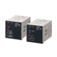
Economical, Compact, High-performance, DIN 48 × 48-mm Ground Fault Relay for Low Voltages
* Information in this page is a reference that you created on the basis of information in the product catalog before the end of production, may be different from the current situation, such as goods for / supported standards options / price / features of the product. Before using, please check the compatibility and safety system.
Related Contents
- Features
- Lineup
- Specifications
- Dimensions
- Catalog / Manual / CAD / Software
last update: November 21, 2022
Ground Fault Relay Ratings
| Type | High-speed models | Delayed models | ||
|---|---|---|---|---|
| Control power supply | 100/110 VAC or 200/220 VAC, 50/60 Hz (same for all) | |||
| Rated current | Depends on the ZCT | |||
| Sensed current | 50% to 100% of the rated sensed current | |||
| Non-operating current | 0% to 50% of the rated sensed current | |||
| Rated short-time current | 2,500 A | |||
| Ground fault indication method | LED (red) | |||
| Test method | Relay operation confirmed using a test button. (Independent of ZCT connection.) | |||
| Reset method | Manual | Either press the reset button or turn the control power supply OFF and ON again. | ||
| Built-in
contacts |
Contact form | SPDT+SPST-NO | ||
| Carrying current | 5 A | |||
| Rated load | cosφ = 1 | cosφ = 0.4 (L/R = 7 ms) | ||
| 240 VAC | 5 A | 2 A | ||
| 110 VDC | 0.3 A | 0.2 A | ||
| 30 VDC | 5 A | 3 A | ||
| Minimum applicable load: 5 VDC, 10 mA (reference value) | ||||
| Power (VA) consumption | 3 VA max. | |||
| Weight | Approx. 110 g | |||
Ground Fault Relay Characteristics
| Type | High-speed models | Delayed models |
|---|---|---|
| Operating time | Less than 0.1 s | 0.3 s/0.8 s (switchable) |
| Inertial non-operating
time |
--- | 0.1 s when set to 0.3 s
0.5 s when set to 0.8 s |
| Control power supply
range |
80% to 110% of the control power supply voltage | |
| Operating temperature
range |
-10 to 55 °C (with no icing) | |
| Operating humidity
range |
45% to 85% (with no condensation) | |
| Insulation resistance | 5 MΩ min. at 500 VDC (between charged parts and the mounting panel) | |
| Dielectric strength | 1,500 VAC, 50/60 Hz for 1 min (between charged parts and the mounting panel) | |
| Lightning impulse
dielectric strength |
1.2/50 μs, 7,000 V (between control power supply terminals) | |
| Lightning impulse
operation failure |
1.2/50 μs, 7,000 V (primary side of ZCT) | |
| Vibration resistance | Destruction: 16.7 Hz, 4-mm double amplitude for 1 min | |
| Shock resistance | 98 m/s2 | |
Note: The range for an operating time of 0.3 s is 0.15 to 0.45 s and the range for an operating time of 0.8 s is 0.6 to 1.2 s.
ZCT (Zero-phase Current Transformer)
| Structure | Indoor through-type models | Indoor separate-type models | |||||||
|---|---|---|---|---|---|---|---|---|---|
| Model | OTG-L21 | OTG-L30 | OTG-L42 | OTG-L68 | OTG-L82 | OTG-L156 | OTG-CN52 | OTG-CN77 | OTG-CN112 |
| Rated current | 50 A | 100 A | 200 A | 400 A | 600 A | 1,000 A | 200 A | 400 A | 600 A |
|
Diameter of through- hole |
21 mm | 30 mm | 42 mm | 68 mm | 82 mm | 156 mm | 52 mm | 77 mm | 112 mm |
| Rated voltage | 600 VAC max., 50/60 Hz, single-phase/three-phase | ||||||||
|
Output terminal polarity |
None (The ZCT's output terminals k and l can be connected to either input terminals 3 or 4 of the Relay.) (See note.) | ||||||||
| Insulation resistance | 100 MΩ min. (between charged metal parts and ground) | ||||||||
| Dielectric strength | 2,200 VAC, 50/60 Hz for 1 min (between charged metal parts and ground) | ||||||||
|
Ambient operating temperature |
-10 to 60 °C (with no icing) | ||||||||
| Weight | Approx. 90 g |
Approx. 130 g |
Approx. 230 g |
Approx. 480 g |
Approx. 700 g |
Approx. 6.6 kg |
Approx. 1.3 kg |
Approx. 2.5 kg |
Approx. 3.5 kg |
Note: Do not connect ZCT output terminals k and l to ground. Doing so may result in damage to the Relay.
last update: November 21, 2022
 Product Category
- Power Supplies / In Addition
-
Measuring / Motor Protective Relays
-
Discontinued
- K6EL
-
Discontinued
-