XW5T-P
DIN Track Push-in Terminal Blocks
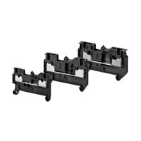
Our Value Design Products Increase the Value of Your Control Panels. Push-in Plus Terminal Blocks to Downsize Control Panels and Save Work.
- Features
- Lineup
- Specifications
- Dimensions
- Catalog / Manual / CAD / Software
last update: July 27, 2020
Ratings and Performance
Ratings
Feed Through Terminal blocks Standard terminals
| Model | XW5T-P1.5-1.1-1 (BL) | XW5T-P2.5-1.1-1 (BL) | XW5T-P4.0-1.1-1 (BL) | ||||
|---|---|---|---|---|---|---|---|
| Appearance and internal
wiring |
1 tier, 1:1
 |
1 tier, 1:1
 |
1 tier, 1:1
 |
||||
| Appli-
cable wire sizes *1 |
Stranded wire | 0.08 mm2 to 1.5 mm2 | 0.14 mm2 to 2.5 mm2 | 0.2 mm2 to 4.0 mm2 | |||
| Solid wire | 0.14 mm2 to 1.5 mm2 | 0.14 mm2 to 4.0 mm2 | 0.2 mm2 to 6.0 mm2 | ||||
| Stranded wire
with ferrule with Plastic sleeve |
0.14 mm2 to 0.75 mm2
(1.5 mm2) *2 |
0.14 mm2 to 2.5 mm2 | 0.25 mm2 to 4.0 mm2 | ||||
| Dimensions | 3.5 × 45 × 30.5 | 5.2 × 48.8 × 35.3 | 6.2 × 56.1 × 35.3 | ||||
| Rated voltage | 500 V | 800 V | |||||
| Rated current *3 | 17.5 A | 24 A | 32 A | ||||
| IEC rated voltage | 500 V | 800 V | 800 V | ||||
| IEC rated current *3 | 17.5 A/1.5 mm2 | 24 A/2.5 mm2 | 32 A/4.0 mm2 | ||||
| Usage Group (UG) | B, C | D | B, C | ||||
| UL rated voltage | 300 V | 51-
150 V |
151-
300 V |
301-
600 V |
600 V | ||
| UL rated current *3 | 15 A/
AWG14 (SOL) 10 A/ AWG16 |
15 A/
AWG14 (SOL) 10 A/ AWG16 |
10 A/
AWG16 |
5 A/
AWG 16-20 |
20 A/AWG12 (SOL),
15 A/AWG14 |
30 A/AWG10 (SOL),
20 A/AWG12 |
|
| Dielectric strength | 1,890 VAC for 1 min
(leakage current: 1 mA max.) |
2,000 VAC for 1 min
(leakage current: 1 mA max.) |
2,000 VAC for 1 min
(leakage current: 1 mA max.) |
||||
| End Cover | XW5E-P1.5-1.1-1 | XW5E-P2.5-1.1-1 | XW5E-P4.0-1.1-1 | ||||
| Special tool | XW4Z-00B | XW4Z-00B | XW4Z-00B | ||||
| Applicable nameplates | XW5Z-P1.5LB[] or commercially
available nameplate with 9.5 mm width and 0.5 mm thickness |
XW5Z-P2.5LB[] or
commercially available nameplate with 9.5 mm width and 0.5 mm thickness |
XW5Z-P4.0LB[] or
commercially available nameplate with 9.5 mm width and 0.5 mm thickness |
||||
| Applicable Short Bars | XW5S-P1.5-[]
([]: Poles = 2, 3, 4, 5 or 10) |
XW5S-P2.5-[]
([]: Poles = 2, 3, 4, 5 or 10) |
XW5S-P4.0-[]
([]: Poles = 2, 3, 4, 5 or 10) |
||||
*1. For the recommended applicable wire ranges, refer to Data Sheet for solid and stranded wires, and to for ferrules.
*2. You can also use ferrules for 1.0 to 1.5 mm2 wires if you use ferrules without insulation sleeve. Refer to Data Sheet for details.
*3. Do not apply more than the rated current to the terminal block.
Feed Through Terminal blocks Multi tiers terminal
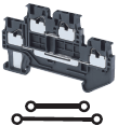
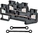
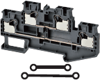
| Model | XW5T-P1.5-1.1-2 (BL) | XW5T-P2.5-1.1-2 (BL) | XW5T-P4.0-1.1-2 (BL) | ||||
|---|---|---|---|---|---|---|---|
| Appearance and internal
wiring |
2 tiers, 1:1
 |
2 tiers, 1:1
 |
2 tiers, 1:1
 |
||||
| Appli-
cable wire sizes *1 |
Stranded wire | 0.08 mm2 to 1.5 mm2 | 0.14 mm2 to 2.5 mm2 | 0.2 mm2 to 4.0 mm2 | |||
| Solid wire | 0.14 mm2 to 1.5 mm2 | 0.14 mm2 to 4.0 mm2 | 0.2 mm2 to 6.0 mm2 | ||||
| Stranded wire
with ferrule with Plastic sleeve |
0.14 mm2 to 0.75 mm2
(1.5 mm2) *2 |
0.14 mm2 to 2.5 mm2 | 0.25 mm2 to 4.0 mm2 | ||||
| Dimensions | 3.5 × 65.7 × 41.1 | 5.2 × 78.8 × 45.9 | 6.2 × 85 × 45.9 | ||||
| Rated voltage | 500 V | 600 V | |||||
| Rated current *3 | 17.5 A | 22 A | 28 A | ||||
| IEC rated voltage | 500 V | ||||||
| IEC rated current *3 | 17.5 A/1.5 mm2 | 22 A/2.5 mm2 | 28 A/4.0 mm2 | ||||
| Usage Group (UG) | B, C | D | B, C | ||||
| UL rated voltage | 300 V | 51-
150 V |
151-
300 V |
301-
600 V |
600 V | ||
| UL rated current *3 | 15 A/
AWG14 (SOL) 10 A/ AWG16 |
15 A/
AWG14 (SOL) 10 A/ AWG16 |
10 A/
AWG16 |
5 A/
AWG 16-20 |
20 A/AWG12 (SOL),
15 A/AWG14 |
30 A/AWG10 (SOL),
20 A/AWG12 |
|
| Dielectric strength | 1,890 VAC for 1 min
(leakage current: 1 mA max.) |
2,000 VAC for 1 min
(leakage current: 1 mA max.) |
|||||
| End Cover | XW5E-P1.5-1.1-2 | XW5E-P2.5-1.1-2 | XW5E-P4.0-1.1-2 | ||||
| Special tool | XW4Z-00B | ||||||
| Applicable nameplates | XW5Z-P1.5LB2 | XW5Z-P2.5LB[] or
commercially available nameplate with 9.5 mm width and 0.5 mm thickness |
XW5Z-P4.0LB[] or
commercially available nameplate with 9.5 mm width and 0.5 mm thickness |
||||
| Applicable Short Bars | XW5S-P1.5-[]
([]: Poles = 2, 3, 4, 5 or 10) |
XW5S-P2.5-[]
([]: Poles = 2, 3, 4, 5 or 10) |
XW5S-P4.0-[]
([]: Poles = 2, 3, 4, 5 or 10) |
||||
*1. For the recommended applicable wire ranges, refer to Data Sheet for solid and stranded wires, and to for ferrules.
*2. You can also use ferrules for 1.0 to 1.5 mm2 wires if you use ferrules without insulation sleeve. Refer to Data Sheet for details.
*3. Do not apply more than the rated current to the terminal block.
Feed Through Terminal blocks Multi conductor terminals
| Model | XW5T-P1.5-1.2-1 (BL) | XW5T-P2.5-1.2-1 (BL) | XW5T-P4.0-1.2-1 (BL) | ||||
|---|---|---|---|---|---|---|---|
| Appearance and internal
wiring |
1 tier, 1:2
 |
1 tier, 1:2
 |
1 tier, 1:2
 |
||||
| Appli-
cable wire sizes *1 |
Stranded wire | 0.08 mm2 to 1.5 mm2 | 0.14 mm2 to 2.5 mm2 | 0.2 mm2 to 4.0 mm2 | |||
| Solid wire | 0.14 mm2 to 1.5 mm2 | 0.14 mm2 to 4.0 mm2 | 0.2 mm2 to 6.0 mm2 | ||||
| Stranded wire
with ferrule with Plastic sleeve |
0.14 mm2 to 0.75 mm2
(1.5 mm2) *2 |
0.14 mm2 to 2.5 mm2 | 0.25 mm2 to 4.0 mm2 | ||||
| Dimensions | 3.5 × 54.1 × 30.5 | 5.2 × 60.5 × 35.3 | 6.2 × 66.5 × 35.3 | ||||
| Rated voltage | 500 V | 800 V | |||||
| Rated current *3 | 17.5 A | 24 A | 32 A | ||||
| IEC rated voltage | 500 V | 800 V | |||||
| IEC rated current *3 | 17.5 A/1.5 mm2 | 24 A/2.5 mm2 | 32 A/4.0 mm2 | ||||
| Usage Group (UG) | B, C | D | B, C | ||||
| UL rated voltage | 300 V | 51-
150 V |
151-
300 V |
301-
600 V |
600 V | ||
| UL rated current *3 | 15 A/
AWG14 (SOL) 10 A/ AWG16 |
15 A/
AWG14 (SOL) 10 A/ AWG16 |
10 A/
AWG16 |
5 A/
AWG 16-20 |
20 A/AWG12 (SOL),
15 A/AWG14 |
30 A/AWG10 (SOL),
20 A/AWG12 |
|
| Dielectric strength | 1,890 VAC for 1 min
(leakage current: 1 mA max.) |
2,000 VAC for 1 min
(leakage current: 1 mA max.) |
|||||
| End Cover | XW5E-P1.5-1.2-1 | XW5E-P2.5-1.2-1 | XW5E-P4.0-1.2-1 | ||||
| Special tool | XW4Z-00B | ||||||
| Applicable nameplates | XW5Z-P1.5LB[] or commercially
available nameplate with 9.5 mm width and 0.5 mm thickness |
XW5Z-P2.5LB[] or
commercially available nameplate with 9.5 mm width and 0.5 mm thickness |
XW5Z-P4.0LB[] or
commercially available nameplate with 9.5 mm width and 0.5 mm thickness |
||||
| Applicable Short Bars | XW5S-P1.5-[]
([]: Poles = 2, 3, 4, 5 or 10) |
XW5S-P2.5-[]
([]: Poles = 2, 3, 4, 5 or 10) |
XW5S-P4.0-[]
([]: Poles = 2, 3, 4, 5 or 10) |
||||
*1. For the recommended applicable wire ranges, refer to Data Sheet for solid and stranded wires, and to for ferrules.
*2. You can also use ferrules for 1.0 to 1.5 mm2 wires if you use ferrules without insulation sleeve. Refer to Data Sheet for details.
*3. Do not apply more than the rated current to the terminal block.
| Model | XW5T-P1.5-2.2-1 (BL) | XW5T-P2.5-2.2-1 (BL) | XW5T-P4.0-2.2-1 (BL) | ||||
|---|---|---|---|---|---|---|---|
| Appearance and internal
wiring |
1 tier, 2:2
 |
1 tier, 2:2
 |
1 tier, 2:2
 |
||||
| Appli-
cable wire sizes *1 |
Stranded wire | 0.08 mm2 to 1.5 mm2 | 0.14 mm2 to 2.5 mm2 | 0.2 mm2 to 4.0 mm2 | |||
| Solid wire | 0.14 mm2 to 1.5 mm2 | 0.14 mm2 to 4.0 mm2 | 0.2 mm2 to 6.0 mm2 | ||||
| Stranded wire
with ferrule with Plastic sleeve |
0.14 mm2 to 0.75 mm2
(1.5 mm2) *2 |
0.14 mm2 to 2.5 mm2 | 0.25 mm2 to 4.0 mm2 | ||||
| Dimensions | 3.5 × 63.2 × 30.5 | 5.2 × 72.2 × 35.3 | 6.2 × 76.9 × 35.3 | ||||
| Rated voltage | 500 V | 800 V | |||||
| Rated current *3 | 17.5 A | 24 A | 32 A | ||||
| IEC rated voltage | 500 V | 800 V | |||||
| IEC rated current *3 | 17.5 A/1.5 mm2 | 24 A/2.5 mm2 | 32 A/4.0 mm2 | ||||
| Usage Group (UG) | B, C | D | B, C | ||||
| UL rated voltage | 300 V | 51-
150 V |
151-
300 V |
301-
600 V |
600 V | ||
| UL rated current *3 | 15 A/
AWG14 (SOL) 10 A/ AWG16 |
15 A/
AWG14 (SOL) 10 A/ AWG16 |
10 A/
AWG16 |
5 A/
AWG 16-20 |
20 A/AWG12 (SOL),
15 A/AWG14 |
30 A/AWG10 (SOL),
20 A/AWG12 |
|
| Dielectric strength | 1,890 VAC for 1 min
(leakage current: 1 mA max.) |
2,000 VAC for 1 min
(leakage current: 1 mA max.) |
|||||
| End Cover | XW5E-P1.5-2.2-1 | XW5E-P2.5-2.2-1 | XW5E-P4.0-2.2-1 | ||||
| Special tool | XW4Z-00B | ||||||
| Applicable nameplates | XW5Z-P1.5LB[] or commercially
available nameplate with 9.5 mm width and 0.5 mm thickness |
XW5Z-P2.5LB[] or
commercially available nameplate with 9.5 mm width and 0.5 mm thickness |
XW5Z-P4.0LB[] or
commercially available nameplate with 9.5 mm width and 0.5 mm thickness |
||||
| Applicable Short Bars | XW5S-P1.5-[]
([]: Poles = 2, 3, 4, 5 or 10) |
XW5S-P2.5-[]
([]: Poles = 2, 3, 4, 5 or 10) |
XW5S-P4.0-[]
([]: Poles = 2, 3, 4, 5 or 10) |
||||
*1. For the recommended applicable wire ranges, refer to Data Sheet for solid and stranded wires, and to for ferrules.
*2. You can also use ferrules for 1.0 to 1.5 mm2 wires if you use ferrules without insulation sleeve. Refer to Data Sheet for details.
*3. Do not apply more than the rated current to the terminal block.
Grounding Terminal blocks Standard terminals
| Model | XW5G-P1.5-1.1-1 | XW5G-P2.5-1.1-1 | XW5G-P4.0-1.1-1 | |
|---|---|---|---|---|
| Appearance and internal
wiring |
1 tier, 1:1
 |
1 tier, 1:1
 |
1 tier, 1:1
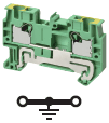 |
|
| Appli-
cable wire sizes *1 |
Stranded wire | 0.08 mm2 to 1.5 mm2 | 0.14 mm2 to 2.5 mm2 | 0.2 mm2 to 4.0 mm2 |
| Solid wire | 0.14 mm2 to 1.5 mm2 | 0.14 mm2 to 4.0 mm2 | 0.2 mm2 to 6.0 mm2 | |
| Stranded wire
with ferrule with Plastic sleeve |
0.14 mm2 to 0.75 mm2
(1.5 mm2) *2 |
0.14 mm2 to 2.5 mm2 | 0.25 mm2 to 4.0 mm2 | |
| Dimensions | 3.5 × 45 × 30.5 | 5.2 × 48.8 × 35.3 | 6.2 × 56.1 × 35.3 | |
| IEC rated voltage | 500 V | 800 V | ||
| UL rated voltage | 600 V | |||
| Dielectric strength | 1,890 VAC for 1 min
(leakage current: 1 mA max.) |
2,000 VAC for 1 min
(leakage current: 1 mA max.) |
||
| End Cover | XW5E-P1.5-1.1-1 | XW5E-P2.5-1.1-1 | XW5E-P4.0-1.1-1 | |
| Special tool | XW4Z-00B | |||
| Applicable nameplates | XW5Z-P1.5LB[] or
commercially available nameplate with 9.5 mm width and 0.5 mm thickness |
XW5Z-P2.5LB[] or
commercially available nameplate with 9.5 mm width and 0.5 mm thickness |
XW5Z-P4.0LB[] or
commercially available nameplate with 9.5 mm width and 0.5 mm thickness |
|
Note: Use a conductive DIN Track when using a Grounding Terminal Block.
OMRON does not offer conductive DIN Tracks. Please use a commercially available product.
*1. For the recommended applicable wire ranges, refer to Data Sheet for solid and stranded wires, and to for ferrules.
*2. You can also use ferrules for 1.0 to 1.5 mm2 wires if you use ferrules without insulation sleeve. Refer to Data Sheet for details.
Grounding Terminal blocks Multi tiers terminal
| Model | XW5G-P1.5-1.1-2 | XW5G-P2.5-1.1-2 | XW5G-P4.0-1.1-2 | |
|---|---|---|---|---|
| Appearance and internal
wiring |
2 tier, 1:1
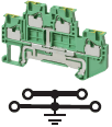 |
2 tiers, 1:1
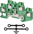 |
2 tiers, 1:1
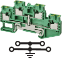 |
|
| Appli-
cable wire sizes *1 |
Stranded wire | 0.08 mm2 to 1.5 mm2 | 0.14 mm2 to 2.5 mm2 | 0.2 mm2 to 4.0 mm2 |
| Solid wire | 0.14 mm2 to 1.5 mm2 | 0.14 mm2 to 4.0 mm2 | 0.2 mm2 to 6.0 mm2 | |
| Stranded wire
with ferrule with Plastic sleeve |
0.14 mm2 to 0.75 mm2
(1.5 mm2) *2 |
0.14 mm2 to 2.5 mm2 | 0.25 mm2 to 4.0 mm2 | |
| Dimensions | 3.5 × 65.7 × 41.1 | 5.2 × 78.8 × 45.9 | 6.2 × 85 × 45.9 | |
| IEC rated voltage | 500 V | |||
| UL rated voltage | 600 V | |||
| Dielectric strength | 1,890 VAC for 1 min
(leakage current: 1 mA max.) |
2,000 VAC for 1 min
(leakage current: 1 mA max.) |
||
| End Cover | XW5E-P1.5-1.1-2 | XW5E-P2.5-1.1-2 | XW5E-P4.0-1.1-2 | |
| Special tool | XW4Z-00B | |||
| Applicable nameplates | XW5Z-P1.5LB2 | XW5Z-P2.5LB[] or
commercially available nameplate with 9.5 mm width and 0.5 mm thickness |
XW5Z-P4.0LB[] or
commercially available nameplate with 9.5 mm width and 0.5 mm thickness |
|
Note: Use a conductive DIN Track when using a Grounding Terminal Block.
OMRON does not offer conductive DIN Tracks. Please use a commercially available product.
*1. For the recommended applicable wire ranges, refer to Data Sheet for solid and stranded wires, and to for ferrules.
*2. You can also use ferrules for 1.0 to 1.5 mm2 wires if you use ferrules without insulation sleeve. Refer to Data Sheet for details.
Grounding Terminal blocks Multi conductor terminals
| Model | XW5G-P1.5-1.2-1 | XW5G-P2.5-1.2-1 | XW5G-P4.0-1.2-1 | |
|---|---|---|---|---|
| Appearance and internal
wiring |
1 tier, 1:2
 |
1 tier, 1:2
 |
1 tier, 1:2
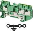 |
|
| Appli-
cable wire sizes *1 |
Stranded wire | 0.08 mm2 to 1.5 mm2 | 0.14 mm2 to 2.5 mm2 | 0.2 mm2 to 4.0 mm2 |
| Solid wire | 0.14 mm2 to 1.5 mm2 | 0.14 mm2 to 4.0 mm2 | 0.2 mm2 to 6.0 mm2 | |
| Stranded wire
with ferrule with Plastic sleeve |
0.14 mm2 to 0.75 mm2
(1.5 mm2) *2 |
0.14 mm2 to 2.5 mm2 | 0.25 mm2 to 4.0 mm2 | |
| Dimensions | 3.5 × 54.1 × 30.5 | 5.2 × 60.5 × 35.3 | 6.2 × 66.5 × 35.3 | |
| IEC rated voltage | 500 V | 800 V | ||
| UL rated voltage | 600 V | 600 V | ||
| Dielectric strength | 1,890 VAC for 1 min
(leakage current: 1 mA max.) |
2,000 VAC for 1 min
(leakage current: 1 mA max.) |
||
| End Cover | XW5E-P1.5-1.2-1 | XW5E-P2.5-1.2-1 | XW5E-P4.0-1.2-1 | |
| Special tool | XW4Z-00B | |||
| Applicable nameplates | XW5Z-P1.5LB[] or
commercially available nameplate with 9.5 mm width and 0.5 mm thickness |
XW5Z-P2.5LB[] or
commercially available nameplate with 9.5 mm width and 0.5 mm thickness |
XW5Z-P4.0LB[] or
commercially available nameplate with 9.5 mm width and 0.5 mm thickness |
|
Note: Use a conductive DIN Track when using a Grounding Terminal Block.
OMRON does not offer conductive DIN Tracks. Please use a commercially available product.
*1. For the recommended applicable wire ranges, refer to Data Sheet for solid and stranded wires, and to for ferrules.
*2. You can also use ferrules for 1.0 to 1.5 mm2 wires if you use ferrules without insulation sleeve. Refer to Data Sheet for details.
| Model | XW5G-P1.5-2.2-1 | XW5G-P2.5-2.2-1 | XW5G-P4.0-2.2-1 | |
|---|---|---|---|---|
| Appearance and internal
wiring |
1 tier, 2:2
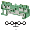 |
1 tier, 2:2
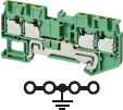 |
1 tier, 2:2
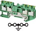 |
|
| Appli-
cable wire sizes *1 |
Stranded wire | 0.08 mm2 to 1.5 mm2 | 0.14 mm2 to 2.5 mm2 | 0.2 mm2 to 4.0 mm2 |
| Solid wire | 0.14 mm2 to 1.5 mm2 | 0.14 mm2 to 4.0 mm2 | 0.2 mm2 to 6.0 mm2 | |
| Stranded wire
with ferrule with Plastic sleeve |
0.14 mm2 to 0.75 mm2
(1.5 mm2) *2 |
0.14 mm2 to 2.5 mm2 | 0.25 mm2 to 4.0 mm2 | |
| Dimensions | 3.5 × 63.2 × 30.5 | 5.2 × 72.2 × 35.3 | 6.2 × 76.9 × 35.3 | |
| IEC rated voltage | 500 V | 800 V | ||
| UL rated voltage | 600 V | |||
| Dielectric strength | 1,890 VAC for 1 min
(leakage current: 1 mA max.) |
2,000 VAC for 1 min
(leakage current: 1 mA max.) |
||
| End Cover | XW5E-P1.5-2.2-1 | XW5E-P2.5-2.2-1 | XW5E-P4.0-2.2-1 | |
| Special tool | XW4Z-00B | |||
| Applicable nameplates | XW5Z-P1.5LB[] or
commercially available nameplate with 9.5 mm width and 0.5 mm thickness |
XW5Z-P2.5LB[] or
commercially available nameplate with 9.5 mm width and 0.5 mm thickness |
XW5Z-P4.0LB[] or
commercially available nameplate with 9.5 mm width and 0.5 mm thickness |
|
Note: Use a conductive DIN Track when using a Grounding Terminal Block.
OMRON does not offer conductive DIN Tracks. Please use a commercially available product.
*1. For the recommended applicable wire ranges, refer to Data Sheet for solid and stranded wires, and to for ferrules.
*2. You can also use ferrules for 1.0 to 1.5 mm2 wires if you use ferrules without insulation sleeve. Refer to Data Sheet for details.
Performance
| Operating temperature | -40 to 55°C (with no condensation or icing) |
|---|---|
| Operating humidity | 5% to 95% |
| Insulating material | PA resin |
| Fire resistance | UL94 V-0 |
| Insertion durability | 50 times |
| Vibration resistance | 10 to 150 Hz, Acceleration of 50 m/s2 for 80 min each in X, Y, and Z directions |
| Shock resistance | 500 m/s2 for 11 ms each in 6 directions 5 times |
| Storage Temperature Range | -40 to 85°C (with no condensation or icing) |
| Storage Humidity Range | 5% to 95% |
Short Bars
| Model | XW5S-P1.5-[] | XW5S-P2.5-[] | XW5S-P4.0-[] |
|---|---|---|---|
| Rated voltage | 500 V | 800 V | |
| Rated current | 17.5 A | 24 A | 32 A |
Standards
Compliant standard
• UL1059
• CSA (C22.2 No.158)
• IEC 60947-7-1
Certification
• cURus (File No. E245101)
last update: July 27, 2020


