3G3MX2-V2
Multi-function Compact Inverter
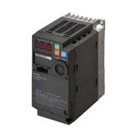
Provides rich features, including simple positioning and PM motor control, for a variety of applications
Related Contents
- Features
- Lineup
- Specifications
- Dimensions
- Catalog / Manual / CAD / Software
last update: February 9, 2026
Standard Specifications
Inverter MX2-series V2 type
ND: Normal load, LD: Light load
3-phase 200-V Class
| Item | 3-phase 200 V | ||||||||||||
|---|---|---|---|---|---|---|---|---|---|---|---|---|---|
| Model (3G3MX2-[]-V2) | A2001 | A2002 | A2004 | A2007 | A2015 | A2022 | A2037 | A2055 | A2075 | A2110 | A2150 | ||
|
Maximum
applicable motor capacity *1 |
kW | ND | 0.1 | 0.2 | 0.4 | 0.75 | 1.5 | 2.2 | 3.7 | 5.5 | 7.5 | 11 | 15 |
| LD | 0.2 | 0.4 | 0.75 | 1.1 | 2.2 | 3.0 | 5.5 | 7.5 | 11 | 15 | 18.5 | ||
| HP | ND | 1/8 | 1/4 | 1/2 | 1 | 2 | 3 | 5 | 7 1/2 | 10 | 15 | 20 | |
| LD | 1/4 | 1/2 | 1 | 1 1/2 | 3 | 4 | 7 1/2 | 10 | 15 | 20 | 25 | ||
|
Rated
output capacity [kVA] |
200 V | ND | 0.2 | 0.5 | 1.0 | 1.7 | 2.7 | 3.8 | 6.0 | 8.6 | 11.4 | 16.2 | 20.7 |
| LD | 0.4 | 0.6 | 1.2 | 2.0 | 3.3 | 4.1 | 6.7 | 10.3 | 13.8 | 19.3 | 23.9 | ||
| 240 V | ND | 0.3 | 0.6 | 1.2 | 2.0 | 3.3 | 4.5 | 7.2 | 10.3 | 13.7 | 19.5 | 24.9 | |
| LD | 0.4 | 0.7 | 1.4 | 2.4 | 3.9 | 4.9 | 8.1 | 12.4 | 16.6 | 23.2 | 28.6 | ||
| Rated input voltage | 3-phase 200 V -15% to 240 V +10%, 50/60 Hz ±5% | ||||||||||||
|
Rated input
current [A] |
ND | 1.0 | 1.6 | 3.3 | 6.0 | 9.0 | 12.7 | 20.5 | 30.8 | 39.6 | 57.1 | 62.6 | |
| LD | 1.2 | 1.9 | 3.9 | 7.2 | 10.8 | 13.9 | 23.0 | 37.0 | 48.0 | 68.0 | 72.0 | ||
| Rated output voltage *2 | 3-phase 200 to 240 V (Less than incoming voltage) | ||||||||||||
|
Rated output
current [A] |
ND | 1.0 | 1.6 | 3.0 | 5.0 | 8.0 | 11.0 | 17.5 | 25.0 | 33.0 | 47.0 | 60.0 | |
| LD | 1.2 | 1.9 | 3.5 | 6.0 | 9.6 | 12.0 | 19.6 | 30.0 | 40.0 | 56.0 | 69.0 | ||
|
Braking torque during
short-time deceleration [%] *3 (discharge resistor no connected) |
50 | 50 | 50 | 50 | 50 | 20 | 20 | 20 | 20 | 10 | 10 | ||
|
Braking
resistor circuit *4 |
Regener-
ative braking |
Built-in braking resistor circuit (discharge resistor separately mounted) | |||||||||||
|
Minimum
connection resistance [Ω] |
100 | 100 | 100 | 50 | 50 | 35 | 35 | 20 | 17 | 17 | 10 | ||
| Cooling method | Self-cooling (without fan) | Forced air cooling (with fan) | |||||||||||
| Weight [kg] | 1.0 | 1.0 | 1.1 | 1.2 | 1.6 | 1.8 | 2.0 | 3.5 | 3.5 | 4.5 | 6.5 | ||
|
Dimensions (Width ×
Height) [mm] |
68 × 128 | 108 × 128 | 140 ×
128 |
140 × 260 | 180 ×
296 |
220 ×
350 |
|||||||
|
Dimensions (Depth)
[mm] |
112 | 125.5 | 148.5 | 173.5 | 158 | 168 | 178 | ||||||
*1. “Applicable motor” represents standard 3-phase motors. When using other types of motors, make sure that the rated
current of the motor does not exceed that of the inverter.
*2. The output voltage decreases as the input voltage drops.
*3. The braking torque during capacitor feedback is the average deceleration torque applied when the motor decelerates in
the shortest deceleration time (when stopped from 50 Hz), not the continuous regenerative torque. The average
deceleration torque varies depending on the motor loss. This value will decrease in operation over 50 Hz.
*4. The usage rate of the regenerative braking function is 10%.
3-phase 400-V Class
| Item | 3-phase 400 V | |||||||||||
|---|---|---|---|---|---|---|---|---|---|---|---|---|
| Model (3G3MX2-[]-V2) | A4004 | A4007 | A4015 | A4022 | A4030 | A4040 | A4055 | A4075 | A4110 | A4150 | ||
|
Maximum
applicable motor capacity *1 |
kW | ND | 0.4 | 0.75 | 1.5 | 2.2 | 3.0 | 4.0 | 5.5 | 7.5 | 11 | 15 |
| LD | 0.75 | 1.5 | 2.2 | 3.0 | 4.0 | 5.5 | 7.5 | 11 | 15 | 18.5 | ||
| HP | ND | 1/2 | 1 | 2 | 3 | 4 | 5 | 7 1/2 | 10 | 15 | 20 | |
| LD | 1 | 2 | 3 | 4 | 5 | 7 1/2 | 10 | 15 | 20 | 25 | ||
|
Rated
output capacity [kVA] |
380 V | ND | 1.1 | 2.2 | 3.1 | 3.6 | 4.7 | 6.0 | 9.7 | 11.8 | 15.7 | 20.4 |
| LD | 1.3 | 2.6 | 3.5 | 4.5 | 5.7 | 7.3 | 11.5 | 15.1 | 20.4 | 25.0 | ||
| 480 V | ND | 1.4 | 2.8 | 3.9 | 4.5 | 5.9 | 7.6 | 12.3 | 14.9 | 19.9 | 25.7 | |
| LD | 1.7 | 3.4 | 4.4 | 5.7 | 7.3 | 9.2 | 14.5 | 19.1 | 25.7 | 31.5 | ||
| Rated input voltage | 3-phase 380 V -15% to 480 V +10%, 50/60 Hz ±5% | |||||||||||
|
Rated input
current [A] |
ND | 1.8 | 3.6 | 5.2 | 6.5 | 7.7 | 11.0 | 16.9 | 18.8 | 29.4 | 35.9 | |
| LD | 2.1 | 4.3 | 5.9 | 8.1 | 9.4 | 13.3 | 20.0 | 24.0 | 38.0 | 44.0 | ||
| Rated output voltage *2 | 3-phase 380 to 480 V (Less than incoming voltage) | |||||||||||
|
Rated output
current [A] |
ND | 1.8 | 3.4 | 4.8 | 5.5 | 7.2 | 9.2 | 14.8 | 18.0 | 24.0 | 31.0 | |
| LD | 2.1 | 4.1 | 5.4 | 6.9 | 8.8 | 11.1 | 17.5 | 23.0 | 31.0 | 38.0 | ||
|
Braking torque during
short-time deceleration [%] *3 (discharge resistor not connected) |
50 | 50 | 50 | 20 | 20 | 20 | 20 | 20 | 10 | 10 | ||
|
Braking
resistor circuit *4 |
Regener-
ative braking |
Built-in braking resistor circuit (discharge resistor separately mounted) | ||||||||||
|
Minimum
connection resistance [Ω] |
180 | 180 | 180 | 100 | 100 | 100 | 70 | 70 | 70 | 35 | ||
| Cooling method | Self-cooling
(without fan) |
Forced air cooling (with fan) | ||||||||||
| Weight [kg] | 1.5 | 1.8 | 1.8 | 1.8 | 2.0 | 2.0 | 3.5 | 3.5 | 4.5 | 4.5 | ||
|
Dimensions (Width ×
Height) [mm] |
108 × 128 | 140 ×
128 |
140 × 260 | 180 × 296 | ||||||||
|
Dimensions (Depth)
[mm] |
146.5 | 173.5 | 158 | 168 | ||||||||
*1. “Applicable motor” represents standard 3-phase motors. When using other types of motors, make sure that the rated
current of the motor does not exceed that of the inverter.
*2. The output voltage decreases as the input voltage drops.
*3. The braking torque during capacitor feedback is the average deceleration torque applied when the motor decelerates in
the shortest deceleration time (when stopped from 50 Hz), not the continuous regenerative torque. The average
deceleration torque varies depending on the motor loss. This value will decrease in operation over 50 Hz.
*4. The usage rate of the regenerative braking function is 10%.
Single-phase 200-V Class
| Item | Single-phase 200 V | |||||||
|---|---|---|---|---|---|---|---|---|
| Model (3G3MX2-[]-V2) | AB001 | AB002 | AB004 | AB007 | AB015 | AB022 | ||
|
Maximum
applicable motor capacity *1 |
kW | ND | 0.1 | 0.2 | 0.4 | 0.75 | 1.5 | 2.2 |
| LD | 0.2 | 0.4 | 0.55 | 1.1 | 2.2 | 3.0 | ||
| HP | ND | 1/8 | 1/4 | 1/2 | 1 | 2 | 3 | |
| LD | 1/4 | 1/2 | 3/4 | 1 1/2 | 3 | 4 | ||
|
Rated output
capacity [kVA] |
200 V | ND | 0.2 | 0.5 | 1.0 | 1.7 | 2.7 | 3.8 |
| LD | 0.4 | 0.6 | 1.2 | 2.0 | 3.3 | 4.1 | ||
| 240 V | ND | 0.3 | 0.6 | 1.2 | 2.0 | 3.3 | 4.5 | |
| LD | 0.4 | 0.7 | 1.4 | 2.4 | 3.9 | 4.9 | ||
| Rated input voltage | Single-phase 200 V -15% to 240 V +10%, 50/60 Hz ±5% | |||||||
| Rated input current [A] | ND | 1.3 | 3.0 | 6.3 | 11.5 | 16.8 | 22.0 | |
| LD | 2.0 | 3.6 | 7.3 | 13.8 | 20.2 | 24.0 | ||
| Rated output voltage *2 | 3-phase 200 to 240 V (Less than incoming voltage) | |||||||
|
Rated output current
[A] |
ND | 1.0 | 1.6 | 3.0 | 5.0 | 8.0 | 11.0 | |
| LD | 1.2 | 1.9 | 3.5 | 6.0 | 9.6 | 12.0 | ||
|
Braking torque during short-
time deceleration [%] *3 (discharge resistor not connected) |
50 | 50 | 50 | 50 | 50 | 20 | ||
|
Braking
resistor circuit *4 |
Regenerative
braking |
Built-in braking resistor circuit (discharge resistor separately mounted) | ||||||
|
Minimum
connection resistance [Ω] |
100 | 100 | 100 | 50 | 50 | 35 | ||
| Cooling method | Self-cooling (without fan) | Forced air cooling (with fan) | ||||||
| Weight [kg] | 1.0 | 1.0 | 1.1 | 1.6 | 1.8 | 1.8 | ||
|
Dimensions (Width × Height)
[mm] |
68 × 128 | 108 × 128 | ||||||
| Dimensions (Depth) [mm] | 112 | 125.5 | 173.5 | |||||
*1. “Applicable motor” represents standard 3-phase motors. When using other types of motors, make sure that the rated
current of the motor does not exceed that of the inverter.
*2. The output voltage decreases as the input voltage drops.
*3. The braking torque during capacitor feedback is the average deceleration torque applied when the motor decelerates in
the shortest deceleration time (when stopped from 50 Hz), not the continuous regenerative torque. The average
deceleration torque varies depending on the motor loss. This value will decrease in operation over 50 Hz.
*4. The usage rate of the regenerative braking function is 10%.
Common Specifications
Inverter MX2-series V2 type
| Item | Specifications | |
|---|---|---|
| Enclosure rating | Open type (IP20) | |
| Control | Control method | Phase-to-phase sinusoidal modulation PWM |
| Output frequency range *1 | 0.01 to 590 Hz | |
| Frequency precision *2 | Digital command: ±0.01% of the maximum frequency,
Analog command: ±0.2% of the maximum frequency (25±10°C) |
|
|
Frequency setting
resolution |
Digital setting: 0.01 Hz,
Analog setting: Maximum frequency × 1/1000 |
|
|
Voltage/Frequency
characteristics |
V/f characteristics (constant torque, reduced torque)
Sensorless vector control, V/f control with speed feedback |
|
|
Overload current rating of
inverter |
Normal-load rating (ND): 150%/60 s
Light-load rating (LD): 120%/60 s |
|
|
Instantaneous
overcurrent protection |
200% of normal-load rating (ND) value | |
|
Acceleration/
Deceleration time |
0.00 to 3600 s (line/curve arbitrary setting), 2nd acceleration/deceleration
setting provided |
|
|
Carrier frequency change
range |
2 to 15 kHz (Derating required) | |
| Starting torque | 200%/0.5 Hz (Sensorless vector control) | |
| DC injection braking | Operates at operating frequency or less during deceleration via STOP
command, at set frequency or less during operation, or via external input (level and time can be set). |
|
| Protective function | Overcurrent, Overvoltage, Undervoltage, Electronic thermal, Temperature
error, Ground-fault current at power-on, Inrush current protection circuit, Overload limit, Incoming overvoltage, External trip, Memory error, CPU error, USP error, Communication error, Overvoltage suppression during deceleration, Power interruption protection, Emergency shutoff, Analog current input (new), STO internal error (new), etc. |
|
|
Input
signal |
Frequency settings | Digital Operator
External analog input signal (variable resistor/0 to 10 VDC/4 to 20 mA), Modbus communication |
| RUN/STOP command | Digital Operator
External digital input signal (3-wire input available), Modbus communication |
|
| Multi-function Input *3 | 7 points (Functions can be selected from among 66) | |
| Analog input *4 | 2 points (FV terminal for voltage: 10 bits/0 to 10 V, FI terminal for current:
10 bits/4 to 20 mA) |
|
| Pulse input | 2 point (32 kHz max., RP terminal: 5 to 24 VDC, S7 terminal: 24 VDC) | |
| Safety input | 2 points (GS1, GS2: Dedicated terminals) | |
|
Output
signal |
Multi-function output *3 | 2 points (P1 and P2 terminal, Functions can be selected from among 47) |
| Relay output *3 | 1 point (SPDT contact (MC, MA, MB), Functions can be selected from among
47) |
|
|
Analog output (Frequency
monitor) *5 |
1 point (AM terminal: 10 bits for voltage, 0 to 10 V) (Frequency or current can
be selected) |
|
| Pulse output | 1 point (MP terminal: 32 kHz max., 0 to 10 V) | |
|
Commu-
nications |
RS-422 | RJ45 connector (for Digital Operator) |
| RS-485 | Control circuit terminal, Modbus communication | |
| USB | USB 2.0, Micro-B connector | |
| Other functions | AVR function, V/f characteristics switching, Upper/Lower limit, Multi-step
speed (16 steps), Starting frequency adjustment, Jogging operation, Carrier frequency adjustment, PID control, Frequency jump, Analog gain/bias adjustment, S-shape acceleration/deceleration, Electronic thermal characteristics/level adjustment, Restart function, Torque boost function, Fault monitor, Soft lock function, Frequency conversion display, USP function, 2nd control function, UP/DOWN, Overcurrent suppression function, etc. |
|
|
General
specifi- cations |
Operating ambient
temperature *6 |
-10 to 50°C (Derating required) |
|
Storage ambient
temperature |
-20 to 65°C (During shipment) | |
|
Operating ambient
humidity |
20% to 90% (with no condensation) | |
| Vibration resistance | 5.9 m/s2 (0.6 G), 10 to 55 Hz | |
| Location | At a maximum altitude of 1,000 m, indoors (without corrosive gases or dust) | |
| Options |
EtherCAT
Communications Unit |
3G3AX-MX2-ECT |
| Other optional equipment | DC reactor, AC reactor, Radio noise filter, Input noise filter, Output noise
filter, Regenerative braking unit, Braking resistor, etc. |
|
*1. If you must use the motor at higher than 50/60 Hz, check the allowable maximum motor speed and other information
with the motor manufacturer.
To run the motor at higher than 400 Hz, use the high-frequency mode.
*2. To achieve stable motor control, the output frequency may exceed the maximum frequency set in the 1st/2nd Maximum
Frequency (A004/A204) by a maximum of 2 Hz.
*3. In the LD (light load) mode and the PM motor mode, the available functions are limited compared with the ND (normal
load) mode. For some parameters, the default data and setting range also differ.
*4. By default, the maximum frequency is adjusted to 9.8 V for a voltage input of 0 to 10 VDC and to 19.8 mA for a current
input of 4 to 20 mA, respectively. If necessary, adjust the default parameter settings. For details, refer to the Multi-
function Compact Inverter 3G3MX2-V2 User’s Manual (Cat. No. I666).
*5. The analog voltage and current values for the multi-function monitor output terminals show values that can only be used
as a guide for analog meter connection. The maximum output value may differ from 10 V or 20 mA due to the variability
of the analog output circuit. If necessary, adjust the default parameter settings. For details, refer to the Multi-function
Compact Inverter 3G3MX2-V2 User’s Manual (Cat. No. I666).
*6. Derating of the rated output current of the Inverter may be required depending on the normal/light load mode selection,
operating ambient temperature, side-by-side installation, and carrier frequency settings.
Use the inverter in an appropriate environment, refer to the Multi-function Compact Inverter 3G3MX2-V2 User’s Manual
(Cat. No. I666).
Applicable Standards
The 3G3MX2-V2 Series complies with following standards.
| Regulation | Applicable Standards | |
|---|---|---|
| CE
UKCA |
EMC | EN 61800-3 |
| Functional safety | EN 61800-5-2, STO SIL3
EN ISO 13849-1, Cat.3/Ple |
|
| Electrical safety | EN 61800-5-1 | |
| Others | Ecodesign, RoHS | |
| UL | US | UL61800-5-1 |
| CA | CSA-C22.2 No.274 | |
| FS | IEC 61800-5-2, STO SIL3
IEC 61508-1 to -7 SIL3 EN ISO 13849-1, Cat.3/Ple |
|
| RCM | EN 61800-3 | |
Communication Unit
MX2-Series EtherCAT Communication Unit 3G3AX-MX2-ECT
This is the communication unit to connect the Multi-function Compact Inverter MX2 to EtherCAT network.
This communication unit passed the conformance test of EtherCAT.
Specifications
| Item | Specifications | |
|---|---|---|
|
General
specifications |
Power supply | Supplied from inverter |
| Enclosure rating | IP20 | |
| Operating ambient temperature | -10 to 50°C | |
| Storage ambient temperature | -20 to 65°C | |
| Operating ambient humidity | 20% to 90% (with no condensation) | |
| Vibration resistance | 5.9 m/s2 (0.6 G), 10 to 55 Hz | |
| Location | At a maximum altitude of 1,000 m, indoors (without corrosive
gases or dust) |
|
| Weight | 100 g max. (Shipping weight: Approx. 130 g) | |
| EC Directives | EMC Directive: EN61800-3
Low Voltage Directive: EN61800-5-1 |
|
| UL/cUL Standard | UL508C | |
| KC | Equipment management number: OMR-MX2-ECT-00001 | |
|
EtherCAT
Communication specifications |
Communications standard | IEC 61158 Type12, IEC 61800-7 CiA 402 drive profile |
| Physical layer | 100BASE-TX (IEEE802.3) | |
| Connector | RJ45 × 2 (shielded type)
ECAT IN: EtherCAT input ECAT OUT: EtherCAT output |
|
| Communications media | Category 5 or higher (cable with double, aluminum tape and
braided shielding) is recommended. |
|
| Communications distance | Distance between nodes: 100 m max. | |
| Process data | Fixed PDO mapping
PDO mapping |
|
| Mailbox (CoE) | Emergency messages, SDO requests, SDO responses, and
SDO information |
|
| Distributed clock | Free-run mode (asynchronous) | |
| LED display | L/A IN (Link/Activity IN) × 1
L/A OUT (Link/Activity OUT) × 1 RUN × 1 ERR × 1 |
|
| CiA402 drive profile | Velocity mode | |
Options
Regenerative Braking Unit (3G3AX-RBU[][])
These products absorb the regenerative energy generated when a load decelerates or an elevating axis descends to prevent overvoltage trip of the inverter.
Used with a Braking Resistor when the deceleration time of the motor is needed to be reduced in the MX2.
Built-in Resistor Type (3G3AX-RBU21/RBU22/RBU41)
| Voltage class | 3-phase 200-V class | 3-phase 400-V class | ||
|---|---|---|---|---|
| Model | 3G3AX-RBU21 | 3G3AX-RBU22 | 3G3AX-RBU41 *1 | |
| Connection resistance | 17 Ω min. | 17 Ω min. | 34 Ω min. | |
| Operating voltage (ON/OFF) | ON: 362.5 ± 5 V
OFF: 355 ± 5 V (-5% or -10% setting available *2) |
ON: 725 ± 5 V
OFF: 710 ± 5 V (-5% or -10% setting available *2) |
||
| Operation indication | LED ON (Lit) | |||
|
Maximum number of units for
parallel interlocking operation *2 |
5 units | |||
| Model | 3G3AX-RBU21 | 3G3AX-RBU22 | 3G3AX-RBU41 *1 | |
|
Cable length between
regenerative braking unit and inverter |
5 m max. | |||
|
Built-in
resistor |
Internal resistance | 120 W 180 Ω | 120 W 20 Ω | 120 W 180 Ω × 2 in series |
|
Allowable
continuous ON time |
10 s max. | 0.5 s max. | 10 s max. | |
|
Allowable operation
cycle |
Cycle 1/10
(ON for 10 s/OFF for 90 s) |
Cycle 1/80
(ON for 0.5 s/OFF for 40 s) |
Cycle 1/10
(ON for 10 s/OFF for 90 s) |
|
| Power consumption | Instantaneous: 0.73 kW
Short-time rating: 120 W |
Instantaneous: 6.6 kW
Short-time rating: 120 W |
Instantaneous: 1.46 kW
Short-time rating: 240 W |
|
|
Protective
function |
Built-in resistor
overheat protection |
Built-in relay specifications
Built-in resistor temperature: Relay trips at approximately 200°C or higher and resets at approximately 170°C or lower. Built-in thermal fuse (No resetting) *3 Contact rating: 250 VAC 200 mA (R load) 12 VDC 500 mA (R load) 42 VDC 200 mA (R load) Minimum load: 1 mA |
||
|
Operating
environ- ment |
Operating ambient
temperature |
-10 to 50°C | ||
|
Storage ambient
temperature |
-20 to 65°C | |||
|
Operating ambient
humidity |
20% to 90% (with no condensation) | |||
|
Vibration
resistance |
5.9 m/s2 (0.6 G) 10 to 55 Hz | |||
| Location | At a maximum altitude of 1,000 m (without corrosive gases or dust) | |||
| Weight [kg] | 1.7 | 2.0 | ||
| Paint color | Munselle 5Y7/1 (except for cooling fan with aluminum base color) | |||
*1. To use the braking resistor (Model: 3G3AX-RBA/RBB/RBC) for the 400-V class regenerative braking unit, be sure to
remove the built-in resistor and connect two resistors of the same model in series. Using a 400-V class regenerative
braking unit with only a single braking resistor connected may cause damage to the braking resistor.
*2. Use DIP switches (SW1 to SW4) on the regenerative braking unit to set the number of connected units.
*3. The built-in resistor has a thermal fuse. If the alarm terminals are not connected, the fuse may blow out in order to
prevent the overheating. If the fuse blows out, the regenerative braking unit must be repaired.
External Resistor Type (3G3AX-RBU23/RBU24/RBU42/RBU43)
| Voltage class | 3-phase 200-V class | 3-phase 400-V class | |||
|---|---|---|---|---|---|
| Model | 3G3AX-RBU23 | 3G3AX-RBU24 | 3G3AX-RBU42 *1 | 3G3AX-RBU43 *1 | |
|
Connection
resistance |
Continuous operation | 6 Ω min. | 4 Ω min. | 24 Ω min. | 12 Ω min. |
|
Short-time operation/
Allowable operation cycle/Allowable continuous ON time |
4 Ω min.
Cycle 1/5 (ON for 2 min/ OFF for 8 min) 2 min |
2 Ω min.
Cycle 1/5 (ON for 2 min/ OFF for 8 min) 2 min |
10 Ω min.
Cycle 1/10 (ON for 10 s/ OFF for 90 s) 10 s |
6 Ω min.
Cycle 1/5 (ON for 2 min/ OFF for 8 min) 2 min |
|
| Operating voltage (ON/OFF) | ON: 362.5 ± 5 V, OFF: 355 ± 5V
(-5% or -10% setting available *2) |
ON: 725 ± 5 V, OFF: 710 ± 5 V
(-5% or -10% setting available *2) |
|||
| Operation indication | LED ON (Lit) | ||||
|
Maximum number of units for
parallel interlocking operation *2 |
2 units | ||||
| Model | 3G3AX-RBU23 | 3G3AX-RBU24 | 3G3AX-RBU42 *1 | 3G3AX-RBU43 *1 | |
|
Cable length between regenerative
braking unit and inverter |
4 m max. | Braking
resistance: 4 Ω or lower for 4 m min. Lower than 4 Ω for 3 m min. |
4 m max. | 4 m max. | |
|
Protective
function |
Internal power module
overheat protection |
Built-in relay specifications
Cooling fin temperature: Relay trips at approximately 100°C or higher. Contact rating: 240 VAC 3 A (R load) 36 VDC 2 A (R load) Minimum load: 5 VDC 50 mA (R load) |
|||
|
Operating
environ- ment |
Operating ambient
temperature |
-10 to 50°C | |||
|
Storage ambient
temperature |
-20 to 65°C | ||||
|
Operating ambient
humidity |
20% to 90% (with no condensation) | ||||
| Vibration resistance | 4.9 m/s2 (0.5 G), 10 to 55 Hz | ||||
| Location | At a maximum altitude of 1,000 m (without corrosive gases or dust) | ||||
| Weight [kg] | 6 | 8 | 2 | 6 | |
| Paint color | Munselle 5Y7/1 (except for cooling fan with aluminum base color) | ||||
*1. To use the braking resistor (Model: 3G3AX-RBA/RBB/RBC) for the 400-V class regenerative braking unit, be sure to
remove the built-in resistor and connect two resistors of the same model in series. Using a 400-V class regenerative
braking unit with only a single braking resistor connected may cause damage to the braking resistor.
*2. Use DIP switches (SW1 to SW4) on the regenerative braking unit to set the number of connected units.
Braking Resistor (3G3AX-RBA/RBB/RBC[][][][])
These products absorb the regenerative energy generated when a load decelerates or an elevating axis descends to prevent overvoltage trip of the inverter.
| Model |
Compact type
(Model: 3G3AX-RBA[][][][]) |
Standard type
(Model: 3G3AX-RBB[][][][]) |
Medium capacity type
(Model: 3G3AX-RBC[][][][]) |
|||||||||
|---|---|---|---|---|---|---|---|---|---|---|---|---|
| 1201 | 1202 | 1203 | 1204 | 2001 | 2002 | 3001 | 4001 | 4001 | 6001 | 12001 | ||
|
Resis-
tance |
Capacity [W] | 120 | 200 | 300 | 400 | 400 | 600 | 1200 | ||||
| Resistance [Ω] | 180 | 100 | 50 | 35 | 180 | 100 | 50 | 35 | 50 | 35 | 17 | |
|
Allowable braking frequency
[%] |
5 | 2.5 | 1.5 | 1.0 | 10 | 7.5 | 7.5 | 7.5 | 10 | |||
|
Allowable continuous braking
time [s] |
20 | 12 | 5 | 3 | 30 | 20 | 10 | |||||
| Weight [kg] | 0.27 | 0.97 | 1.68 | 2.85 | 2.5 | 3.6 | 6.5 | |||||
| Error detection function | Built-in thermal (Contact capacity: 240 VAC 2 A max.,
Minimum current: 5 mA) Normally ON (NC contact) Built-in thermal fuse (No resetting) |
Built-in thermal relay:
Normally ON (NC contact) Contact capacity: 240 VAC 3 A resistance load)/0.2 A (L load), 36 VDC 2 A (resistance load) |
||||||||||
|
General
specifi- cations |
Operating ambient
temperature |
-10 to 50°C | ||||||||||
|
Storage ambient
temperature |
-20 to 65°C | |||||||||||
|
Operating ambient
humidity |
20% to 90% (with no condensation) | |||||||||||
| Vibration resistance | 5.9 m/s2 (0.6 G), 10 to 55 Hz | |||||||||||
| Location | At a maximum altitude of 1,000 m (without corrosive gases or dust) | |||||||||||
| Cooling method | Self-cooling | |||||||||||
Note: 1. When using the Braking Resistor (Model: 3G3AX-RBA/RBB/RBC) with a 400-V class inverter or Regenerative
Braking Unit (Model: 3G3AX-RBU41/RBU42/RBU43), be sure to connect two braking resistors of the same model in
series. Using the Regenerative Braking Unit with only one braking resistor connected may cause damage to the
braking resistor.
DC Reactor (3G3AX-DL[][][][])
Use these reactors to suppress harmonics generated from the inverter.
| Inverter | DC reactor specifications | |||||||||
|---|---|---|---|---|---|---|---|---|---|---|
|
Voltage
class |
Max.
appli- cable motor capac- ity [kW] |
Model |
Normal/
Light load mode |
Max.
appli- cable motor capac- ity [kW] |
Rated
input cur- rent [A] |
Model |
Induc-
tance [mH] |
Heat
gener- ation [W] |
Operating
ambient tempera- ture/ humidity |
Location |
| 3-
phase 200-V class |
0.1 | 3G3MX2-
A2001-V2 |
Normal load *1 | 0.1 | 1.0 | 3G3AX-
DL2002 |
21.4 | 8 | -10 to
50°C 20% to 90% |
At an
altitude of 1,000 m max.; indoors (without corrosive gases or dust) |
| Light load | 0.2 | 1.2 | ||||||||
| 0.2 | 3G3MX2-
A2002-V2 |
Normal load *1 | 0.2 | 1.6 | ||||||
| Light load | 0.4 | 1.9 | 3G3AX-
DL2004 |
10.7 | ||||||
| 0.4 | 3G3MX2-
A2004-V2 |
Normal load *1 | 0.4 | 3.3 | ||||||
| Light load | 0.75 | 3.9 | 3G3AX-
DL2007 |
6.75 | 10 | |||||
| 0.75 | 3G3MX2-
A2007-V2 |
Normal load *1 | 0.75 | 6.0 | ||||||
| Light load | 1.1 | 7.2 | 3G3AX-
DL2015 |
3.51 | ||||||
| 1.5 | 3G3MX2-
A2015-V2 |
Normal load *1 | 1.5 | 9.0 | ||||||
| Light load | 2.2 | 10.8 | 3G3AX-
DL2022 |
2.51 | 13 | |||||
| 2.2 | 3G3MX2-
A2022-V2 |
Normal load *1 | 2.2 | 12.7 | ||||||
| Light load | 3.0 | 13.9 | 3G3AX-
DL2037 |
1.60 | 20 | |||||
| 3.7 | 3G3MX2-
A2037-V2 |
Normal load *1 | 3.7 | 20.5 | ||||||
| Light load | 5.5 | 23.0 | 3G3AX-
DL2055 |
1.11 | 26 | |||||
| 5.5 | 3G3MX2-
A2055-V2 |
Normal load *1 | 5.5 | 30.8 | 3G3AX-
DL2075 |
0.84 | 36 | |||
| Light load | 7.5 | 37.0 | ||||||||
| 7.5 | 3G3MX2-
A2075-V2 |
Normal load *1 | 7.5 | 39.6 | ||||||
| Light load | 11 | 48.0 | 3G3AX-
DL2110 |
0.59 | 52 | |||||
| 11 | 3G3MX2-
A2110-V2 |
Normal load *1 | 11 | 57.1 | ||||||
| Light load | 15 | 68.0 | 3G3AX-
DL2150 |
0.44 | 60 | |||||
| 15 | 3G3MX2-
A2150-V2 |
Normal load *1 | 15 | 62.6 | ||||||
| Light load | 18.5 | 72.0 | 3G3AX-
DL2220 |
0.30 | 63 | |||||
| Single-
phase 200-V Class |
0.1 | 3G3MX2-
AB001-V2 |
Normal load *1 | 0.1 | 1.3 | 3G3AX-
DL2002 |
21.4 | 8 | -10 to
50°C 20% to 90% |
At an
altitude of 1,000 m max.; indoors (without corrosive gases or dust) |
| Light load | 0.2 | 2.0 | ||||||||
| 0.2 | 3G3MX2-
AB002-V2 |
Normal load *1 | 0.2 | 3.0 | ||||||
| Light load | 0.4 | 3.6 | 3G3AX-
DL2004 |
10.7 | ||||||
| 0.4 | 3G3MX2-
AB004-V2 |
Normal load *1 | 0.4 | 6.3 | ||||||
| Light load | 0.55 | 7.3 | 3G3AX-
DL2007 |
6.75 | 10 | |||||
| 0.75 | 3G3MX2-
AB007-V2 |
Normal load *1 | 0.75 | 11.5 | ||||||
| Light load | 1.1 | 13.8 | 3G3AX-
DL2015 |
3.51 | ||||||
| 1.5 | 3G3MX2-
AB015-V2 |
Normal load *1 | 1.5 | 16.8 | ||||||
| Light load | 2.2 | 20.2 | 3G3AX-
DL2022 |
2.51 | 13 | |||||
| 2.2 | 3G3MX2-
AB022-V2 |
Normal load *1 | 2.2 | 22.0 | ||||||
| Light load | 3.0 | 24.0 | 3G3AX-
DL2037 |
1.60 | 20 | |||||
| 3-
phase 400-V class |
0.4 | 3G3MX2-
A4004-V2 |
Normal load *1 | 0.4 | 1.8 | 3G3AX-
DL4004 |
43.0 | 10 | -10 to
50°C 20% to 90% |
At an
altitude of 1,000 m max.; indoors (without corrosive gases or dust) |
| Light load | 0.75 | 2.1 | 3G3AX-
DL4007 |
27.0 | ||||||
| 0.75 | 3G3MX2-
A4007-V2 |
Normal load *1 | 0.75 | 3.6 | ||||||
| Light load | 1.5 | 4.3 | 3G3AX-
DL4015 |
14.0 | ||||||
| 1.5 | 3G3MX2-
A4015-V2 |
Normal load *1 | 1.5 | 5.2 | ||||||
| Light load | 2.2 | 5.9 | 3G3AX-
DL4022 |
10.1 | 13 | |||||
| 2.2 | 3G3MX2-
A4022-V2 |
Normal load *1 | 2.2 | 6.5 | ||||||
| Light load | 3.0 | 8.1 | 3G3AX-
DL4037 |
6.4 | 20 | |||||
| 3.0 | 3G3MX2-
A4030-V2 |
Normal load *1 | 3.0 | 7.7 | ||||||
| Light load | 4.0 | 9.4 | ||||||||
| 4.0 | 3G3MX2-
A4040-V2 |
Normal load *1 | 4.0 | 11.0 | ||||||
| Light load | 5.5 | 13.3 | 3G3AX-
DL4055 |
4.41 | 26 | |||||
| 5.5 | 3G3MX2-
A4055-V2 |
Normal load *1 | 5.5 | 16.9 | ||||||
| Light load | 7.5 | 20.0 | 3G3AX-
DL4075 |
3.35 | 36 | |||||
| 7.5 | 3G3MX2-
A4075-V2 |
Normal load *1 | 7.5 | 18.8 | ||||||
| Light load | 11 | 24.0 | 3G3AX-
DL4110 |
2.33 | 52 | |||||
| 11 | 3G3MX2-
A4110-V2 |
Normal load *1 | 11 | 29.4 | ||||||
| Light load | 15 | 38.0 | 3G3AX-
DL4150 |
1.75 | 60 | |||||
| 15 | 3G3MX2-
A4150-V2 |
Normal load *1 | 15 | 35.9 | ||||||
| Light load | 18.5 | 44.0 | 3G3AX-
DL4220 |
1.2 | 67 | |||||
*1. The DC reactor model for the normal load mode is selected with reference to the rated current value of a general-
purpose motor, which is 85% of the rated output current of the Inverter. If you intend to constantly drive a motor whose
rated current value exceeds 85% of the rated output current of the inverter, use the DC reactor model selected for the
light-load mode.
AC Reactor (3G3AX-AL[][][][])
Use these reactors to suppress harmonics generated from the inverter.
| Inverter | AC reactor specifications | |||||||||
|---|---|---|---|---|---|---|---|---|---|---|
|
Voltage
class |
Max.
appli- cable motor capacity [kW] |
Model |
Normal/
Light load mode |
Max.
appli- cable motor capacity [kW] |
Rated
input current [A] |
Model |
Induc-
tance [mH] |
Heat
gener- ation [W] |
Operating
ambient tempera- ture/ humidity |
Location |
| 3-phase
200-V class |
0.1 | 3G3MX2-
A2001-V2 |
Normal load | 0.1 | 1.0 | 3G3AX-
AL2025 |
2.8 | 12 | -10 to
50°C 20% to 90% |
At an
altitude of 1,000 m max.; indoors (without corrosive gases or dust) |
| Light load | 0.2 | 1.2 | ||||||||
| 0.2 | 3G3MX2-
A2002-V2 |
Normal load | 0.2 | 1.6 | ||||||
| Light load | 0.4 | 1.9 | ||||||||
| 0.4 | 3G3MX2-
A2004-V2 |
Normal load | 0.4 | 3.3 | ||||||
| Light load | 0.75 | 3.9 | ||||||||
| 0.75 | 3G3MX2-
A2007-V2 |
Normal load | 0.75 | 6.0 | ||||||
| Light load | 1.1 | 7.2 | ||||||||
| 1.5 | 3G3MX2-
A2015-V2 |
Normal load | 1.5 | 9.0 | ||||||
| Light load | 2.2 | 10.8 | 3G3AX-
AL2055 |
0.88 | 25 | |||||
| 2.2 | 3G3MX2-
A2022-V2 |
Normal load | 2.2 | 12.7 | ||||||
| Light load | 3.0 | 13.9 | ||||||||
| 3.7 | 3G3MX2-
A2037-V2 |
Normal load | 3.7 | 20.5 | 3G3AX-
AL2110 |
0.35 | 50 | |||
| Light load | 5.5 | 23.0 | ||||||||
| 5.5 | 3G3MX2-
A2055-V2 |
Normal load | 5.5 | 30.8 | ||||||
| Light load | 7.5 | 37.0 | ||||||||
| 7.5 | 3G3MX2-
A2075-V2 |
Normal load | 7.5 | 39.6 | 3G3AX-
AL2220 |
0.18 | 50 | |||
| Light load | 11 | 48.0 | ||||||||
| 11 | 3G3MX2-
A2110-V2 |
Normal load | 11 | 57.1 | ||||||
| Light load | 15 | 68.0 | ||||||||
| 15 | 3G3MX2-
A2150-V2 |
Normal load | 15 | 62.6 | ||||||
| Light load | 18.5 | 72.0 | 3G3AX-
AL2330 |
0.09 | 85 | |||||
| Single-
phase 200-V Class |
0.1 | 3G3MX2-
AB001-V2 |
Normal load | 0.1 | 1.3 | 3G3AX-
AL2025 |
2.8 | 12 | -10 to
50°C 20% to 90% |
At an
altitude of 1,000 m max.; indoors (without corrosive gases or dust) |
| Light load | 0.2 | 2.0 | ||||||||
| 0.2 | 3G3MX2-
AB002-V2 |
Normal load | 0.2 | 3.0 | ||||||
| Light load | 0.4 | 3.6 | ||||||||
| 0.4 | 3G3MX2-
AB004-V2 |
Normal load | 0.4 | 6.3 | ||||||
| Light load | 0.55 | 7.3 | ||||||||
| 0.75 | 3G3MX2-
AB007-V2 |
Normal load | 0.75 | 11.5 | 3G3AX-
AL2055 |
0.88 | 25 | |||
| Light load | 1.1 | 13.8 | ||||||||
| 1.5 | 3G3MX2-
AB015-V2 |
Normal load | 1.5 | 16.8 | ||||||
| Light load | 2.2 | 20.2 | 3G3AX-
AL2110 |
0.35 | 50 | |||||
| 2.2 | 3G3MX2-
AB022-V2 |
Normal load | 2.2 | 22.0 | ||||||
| Light load | 3.0 | 24.0 | ||||||||
| 3-phase
400-V class |
0.4 | 3G3MX2-
A4004-V2 |
Normal load | 0.4 | 1.8 | 3G3AX-
AL4025 |
7.7 | 12 | -10 to
50°C 20% to 90% |
At an
altitude of 1,000 m max.; indoors (without corrosive gases or dust) |
| Light load | 0.75 | 2.1 | ||||||||
| 0.75 | 3G3MX2-
A4007-V2 |
Normal load | 0.75 | 3.6 | ||||||
| Light load | 1.5 | 4.3 | ||||||||
| 1.5 | 3G3MX2-
A4015-V2 |
Normal load | 1.5 | 5.2 | ||||||
| Light load | 2.2 | 5.9 | ||||||||
| 2.2 | 3G3MX2-
A4022-V2 |
Normal load | 2.2 | 6.5 | 3G3AX-
AL4055 |
3.5 | 25 | |||
| Light load | 3.0 | 8.1 | ||||||||
| 3.0 | 3G3MX2-
A4030-V2 |
Normal load | 3.0 | 7.7 | ||||||
| Light load | 4.0 | 9.4 | ||||||||
| 4.0 | 3G3MX2-
A4040-V2 |
Normal load | 4.0 | 11.0 | 3G3AX-
AL4110 |
1.3 | 50 | |||
| Light load | 5.5 | 13.3 | ||||||||
| 5.5 | 3G3MX2-
A4055-V2 |
Normal load | 5.5 | 16.9 | ||||||
| Light load | 7.5 | 20.0 | ||||||||
| 7.5 | 3G3MX2-
A4075-V2 |
Normal load | 7.5 | 18.8 | ||||||
| Light load | 11 | 24.0 | 3G3AX-
AL4220 |
0.74 | 60 | |||||
| 11 | 3G3MX2-
A4110-V2 |
Normal load | 11 | 29.4 | ||||||
| Light load | 15 | 38.0 | 3G3AX-
AL4330 |
0.36 | 90 | |||||
| 15 | 3G3MX2-
A4150-V2 |
Normal load | 15 | 35.9 | ||||||
| Light load | 18.5 | 44.0 | ||||||||
Input Noise Filter (3G3AX-NFI[][])
Use this filter to reduce the conductive noise generated in the inverter and transmitted to power supply lines.
| Inverter | Input noise filter specifications | |||||||||
|---|---|---|---|---|---|---|---|---|---|---|
|
Voltage
class |
Max.
appli- cable motor capac- ity [kW] |
Model |
Normal/
Light load mode |
Max.
appli- cable motor capac- ity [kW] |
Rated
input cur- rent [A] |
Model |
Max.
input voltage |
Rated
input current (at 50°C) |
Heat
gener- ation [W] |
Leakage
current (at 60 Hz) |
| 3-phase
200-V Class |
0.1 | 3G3MX2-
A2001-V2 |
Normal load | 0.1 | 1.0 | 3G3AX-NFI21 | 250
VAC +10% |
6 A | 3 | 1.5 mA
max. (250 VAC) |
| Light load | 0.2 | 1.2 | ||||||||
| 0.2 | 3G3MX2-
A2002-V2 |
Normal load | 0.2 | 1.6 | ||||||
| Light load | 0.4 | 1.9 | ||||||||
| 0.4 | 3G3MX2-
A2004-V2 |
Normal load | 0.4 | 3.3 | ||||||
| Light load | 0.75 | 3.9 | ||||||||
| 0.75 | 3G3MX2-
A2007-V2 |
Normal load | 0.75 | 6.0 | 3G3AX-NFI22 | 10 A | 4 | |||
| Light load | 1.1 | 7.2 | ||||||||
| 1.5 | 3G3MX2-
A2015-V2 |
Normal load | 1.5 | 9.0 | ||||||
| Light load | 2.2 | 10.8 | 3G3AX-NFI23 | 20 A | 6 | |||||
| 2.2 | 3G3MX2-
A2022-V2 |
Normal load | 2.2 | 12.7 | ||||||
| Light load | 3.0 | 13.9 | ||||||||
| 3.7 | 3G3MX2-
A2037-V2 |
Normal load | 3.7 | 20.5 | 3G3AX-NFI24 | 30 A | 9 | |||
| Light load | 5.5 | 23.0 | ||||||||
| 5.5 | 3G3MX2-
A2055-V2 |
Normal load | 5.5 | 30.8 | 3G3AX-NFI25 | 40 A | 11 | |||
| Light load | 7.5 | 37.0 | ||||||||
| 7.5 | 3G3MX2-
A2075-V2 |
Normal load | 7.5 | 39.6 | ||||||
| Light load | 11 | 48.0 | 3G3AX-NFI26 | 60 A | 17 | |||||
| 11 | 3G3MX2-
A2110-V2 |
Normal load | 11 | 57.1 | ||||||
| Light load | 15 | 68.0 | 3G3AX-NFI27 | 80 A | 21 | |||||
| 15 | 3G3MX2-
A2150-V2 |
Normal load | 15 | 62.6 | ||||||
| Light load | 18.5 | 72.0 | ||||||||
| Single-
phase 200-V Class |
0.1 | 3G3MX2-
AB001-V2 |
Normal load | 0.1 | 1.3 | 3G3AX-NFI21 | 250
VAC +10% |
6 A | 3 | 1.5 mA
max. (250 VAC) |
| Light load | 0.2 | 2.0 | ||||||||
| 0.2 | 3G3MX2-
AB002-V2 |
Normal load | 0.2 | 3.0 | ||||||
| Light load | 0.4 | 3.6 | ||||||||
| 0.4 | 3G3MX2-
AB004-V2 |
Normal load | 0.4 | 6.3 | 3G3AX-NFI22 | 10 A | 4 | |||
| Light load | 0.55 | 7.3 | ||||||||
| 0.75 | 3G3MX2-
AB007-V2 |
Normal load | 0.75 | 11.5 | 3G3AX-NFI23 | 20 A | 6 | |||
| Light load | 1.1 | 13.8 | ||||||||
| 1.5 | 3G3MX2-
AB015-V2 |
Normal load | 1.5 | 16.8 | ||||||
| Light load | 2.2 | 20.2 | 3G3AX-NFI24 | 30 A | 9 | |||||
| 2.2 | 3G3MX2-
AB022-V2 |
Normal load | 2.2 | 22.0 | ||||||
| Light load | 3.0 | 24.0 | ||||||||
| 3-phase
400-V class |
0.4 | 3G3MX2-
A4004-V2 |
Normal load | 0.4 | 1.8 | 3G3AX-NFI41 | 480
VAC +10% |
7 A | 2 | 7.5 mA
max. (480 VAC) |
| Light load | 0.75 | 2.1 | ||||||||
| 0.75 | 3G3MX2-
A4007-V2 |
Normal load | 0.75 | 3.6 | ||||||
| Light load | 1.5 | 4.3 | ||||||||
| 1.5 | 3G3MX2-
A4015-V2 |
Normal load | 1.5 | 5.2 | ||||||
| Light load | 2.2 | 5.9 | ||||||||
| 2.2 | 3G3MX2-
A4022-V2 |
Normal load | 2.2 | 6.5 | ||||||
| Light load | 3.0 | 8.1 | 3G3AX-NFI42 | 10 A | 4 | |||||
| 3.0 | 3G3MX2-
A4030-V2 |
Normal load | 3.0 | 7.7 | ||||||
| Light load | 4.0 | 9.4 | ||||||||
| 4.0 | 3G3MX2-
A4040-V2 |
Normal load | 4.0 | 11.0 | 3G3AX-NFI43 | 20 A | 6 | |||
| Light load | 5.5 | 13.3 | ||||||||
| 5.5 | 3G3MX2-
A4055-V2 |
Normal load | 5.5 | 16.9 | ||||||
| Light load | 7.5 | 20.0 | ||||||||
| 7.5 | 3G3MX2-
A4075-V2 |
Normal load | 7.5 | 18.8 | ||||||
| Light load | 11 | 24.0 | 3G3AX-NFI44 | 30 A | 9 | |||||
| 11 | 3G3MX2-
A4110-V2 |
Normal load | 11 | 29.4 | ||||||
| Light load | 15 | 38.0 | 3G3AX-NFI45 | 40 A | 11 | |||||
| 15 | 3G3MX2-
A4150-V2 |
Normal load | 15 | 35.9 | ||||||
| Light load | 18.5 | 44.0 | 3G3AX-NFI46 | 50 A | 12 | |||||
Output Noise Filter (3G3AX-NFO[][])
Use this filter to reduce the conductive noise generated in the inverter and transmitted to the motor side wires.
| Inverter | Output noise filter specifications | ||||||||
|---|---|---|---|---|---|---|---|---|---|
|
Voltage
class |
Max.
appli- cable motor capac- ity [kW] |
Model |
Normal/
Light load mode |
Max.
appli- cable motor capac- ity [kW] |
Rated
output current [A] |
Model |
Rated
voltage |
Rated
input current [A] |
Weight
[kg] |
| 3-phase
200-V class |
0.1 | 3G3MX2-
A2001-V2 |
Normal load | 0.1 | 1.0 | 3G3AX-NFO01 | 500
VAC |
6 | 0.7 |
| Light load | 0.2 | 1.2 | |||||||
| 0.2 | 3G3MX2-
A2002-V2 |
Normal load | 0.2 | 1.6 | |||||
| Light load | 0.4 | 1.9 | |||||||
| 0.4 | 3G3MX2-
A2004-V2 |
Normal load | 0.4 | 3.0 | |||||
| Light load | 0.75 | 3.5 | |||||||
| 0.75 | 3G3MX2-
A2007-V2 |
Normal load | 0.75 | 5.0 | |||||
| Light load | 1.1 | 6.0 | 3G3AX-NFO02 | 12 | 0.9 | ||||
| 1.5 | 3G3MX2-
A2015-V2 |
Normal load | 1.5 | 8.0 | |||||
| Light load | 2.2 | 9.6 | |||||||
| 2.2 | 3G3MX2-
A2022-V2 |
Normal load | 2.2 | 11.0 | |||||
| Light load | 3.0 | 12.0 | 3G3AX-NFO03 | 25 | 2.1 | ||||
| 3.7 | 3G3MX2-
A2037-V2 |
Normal load | 3.7 | 17.5 | |||||
| Light load | 5.5 | 19.6 | |||||||
| 5.5 | 3G3MX2-
A2055-V2 |
Normal load | 5.5 | 25.0 | |||||
| Light load | 7.5 | 30.0 | 3G3AX-NFO04 | 50 | 3.7 | ||||
| 7.5 | 3G3MX2-
A2075-V2 |
Normal load | 7.5 | 33.0 | |||||
| Light load | 11 | 40.0 | |||||||
| 11 | 3G3MX2-
A2110-V2 |
Normal load | 11 | 47.0 | |||||
| Light load | 15 | 56.0 | 3G3AX-NFO05 | 75 | 5.7 | ||||
| 15 | 3G3MX2-
A2150-V2 |
Normal load | 15 | 60.0 | |||||
| Light load | 18.5 | 69.0 | |||||||
| Single-phase
200-V class |
0.1 | 3G3MX2-
AB001-V2 |
Normal load | 0.1 | 1.0 | 3G3AX-NFO01 | 500
VAC |
6 | 0.7 |
| Light load | 0.2 | 1.2 | |||||||
| 0.2 | 3G3MX2-
AB002-V2 |
Normal load | 0.2 | 1.6 | |||||
| Light load | 0.4 | 1.9 | |||||||
| 0.4 | 3G3MX2-
AB004-V2 |
Normal load | 0.4 | 3.0 | |||||
| Light load | 0.55 | 3.5 | |||||||
| 0.75 | 3G3MX2-
AB007-V2 |
Normal load | 0.75 | 5.0 | |||||
| Light load | 1.1 | 6.0 | 3G3AX-NFO02 | 12 | 0.9 | ||||
| 1.5 | 3G3MX2-
AB015-V2 |
Normal load | 1.5 | 8.0 | |||||
| Light load | 2.2 | 9.6 | |||||||
| 2.2 | 3G3MX2-
AB022-V2 |
Normal load | 2.2 | 11.0 | |||||
| Light load | 3.0 | 12.0 | 3G3AX-NFO03 | 25 | 2.1 | ||||
| 3-phase
400-V class |
0.4 | 3G3MX2-
A4004-V2 |
Normal load | 0.4 | 1.8 | 3G3AX-NFO01 | 500
VAC |
6 | 0.7 |
| Light load | 0.75 | 2.1 | |||||||
| 0.75 | 3G3MX2-
A4007-V2 |
Normal load | 0.75 | 3.4 | |||||
| Light load | 1.5 | 4.1 | |||||||
| 1.5 | 3G3MX2-
A4015-V2 |
Normal load | 1.5 | 4.8 | |||||
| Light load | 2.2 | 5.4 | |||||||
| 2.2 | 3G3MX2-
A4022-V2 |
Normal load | 2.2 | 5.5 | |||||
| Light load | 3.0 | 6.9 | 3G3AX-NFO02 | 12 | 0.9 | ||||
| 3.0 | 3G3MX2-
A4030-V2 |
Normal load | 3.0 | 7.2 | |||||
| Light load | 4.0 | 8.8 | |||||||
| 4.0 | 3G3MX2-
A4040-V2 |
Normal load | 4.0 | 9.2 | |||||
| Light load | 5.5 | 11.1 | 3G3AX-NFO03 | 25 | 2.1 | ||||
| 5.5 | 3G3MX2-
A4055-V2 |
Normal load | 5.5 | 14.8 | |||||
| Light load | 7.5 | 17.5 | |||||||
| 7.5 | 3G3MX2-
A4075-V2 |
Normal load | 7.5 | 18.0 | |||||
| Light load | 11 | 23.0 | |||||||
| 11 | 3G3MX2-
A4110-V2 |
Normal load | 11 | 24.0 | |||||
| Light load | 15 | 31.0 | 3G3AX-NFO04 | 50 | 3.7 | ||||
| 15 | 3G3MX2-
A4150-V2 |
Normal load | 15 | 31.0 | |||||
| Light load | 18.5 | 38.0 | |||||||
Note: 1. The maximum frequency for the Output Noise Filter is 400 Hz.
Radio Noise Filter (3G3AX-ZCL[])
Use this filter to reduce the radiated noise generated in the inverter and emitted from the power-supply line side and motor side wires.
Select the radio noise filter according to the maximum applicable motor capacity for the normal/light load mode of the Inverter.
• The recommended number of turns is 4. If it is not possible to wind the wire 4 turns due to the limitation of the wire size,
decrease the number to 3, 2, and so on. When the wire can be wound only a single turn, use 4 or more filters side by
side, with each wire wound in the same direction.
• The number of turns should be limited to approximately 8, although the filtering effect is larger with a larger number of
turns. Exceeding this limit may cause negative effects.
3G3AX-ZCL1
3G3AX-ZCL2
Digital Operator (3G3AX-OP01)
In addition to the Digital Operator as standard equipment, the following Digital Operator products are also available. This LED Digital Operator has a volume control to adjust frequency reference.
3G3AX-OP01
| Item | Specifications |
|---|---|
| Display | LED digital display |
| External Dimensions | 55 (H) × 70 (W) × 10 (D) mm |
| Weight | 100 g max. |
| Operating ambient temperature | -10 to 50°C |
| Operating ambient humidity | 20% to 90% (with no condensation) |
| Storage ambient temperature | -20 to 65°C |
| Location | At a maximum altitude of 1,000 m (without corrosive gases or dust) |
| Others | Built-in volume control for frequency setting |
Digital Operator Cable (3G3AX-OPCN[])
| Item | Specifications |
|---|---|
| Connector | RJ45 connector |
| Cable | EIA568-compliant cable (UTP category 5) |
last update: February 9, 2026